
Magnetic disk drive with heater to control flying height and manufacturing method thereof

a magnetic disk drive and heater technology, applied in the direction of magnetic recording, recording carrier construction details, electrical apparatus construction details, etc., can solve the problems of inability to improve productivity and long time to determine control parameters, and achieve the effect of improving the productivity of the magnetic disk drive, high degree of accuracy, and good performance of the magnetic head

Inactive Publication Date: 2009-01-20
HITACHI GLOBAL STORAGE TECH NETHERLANDS BV
View PDF6 Cites 14 Cited by
  • Summary
  • Abstract
  • Description
  • Claims
  • Application Information

AI Technical Summary

Benefits of technology

This approach enables accurate flying height control and enhanced productivity by minimizing the time required to determine control parameters, ensuring optimal performance without the need for extensive error rate measurements across the entire operation range.

Problems solved by technology

However, if the method in which the read-and-write error rate and the like are measured over the whole operation guarantee range is used to determine the control parameters, it takes a long time to determine the control parameters.
Accordingly, it is not possible to improve the productivity.

Method used


Image

  • Magnetic disk drive with heater to control flying height and manufacturing method thereof
  • Magnetic disk drive with heater to control flying height and manufacturing method thereof
  • Magnetic disk drive with heater to control flying height and manufacturing method thereof

Examples


modified example 1

of How to Determine Control Parameters

[0063]In the description up to this point, the constant values of the control parameters are predetermined in accordance with the respective operating conditions. However, after determination of the operating conditions, a test may also be repeatedly performed so as to determine the control parameters in further detail. This makes it possible to adjust the flying height with higher accuracy.

[0064]For example, for the above-mentioned examples, the following is to be performed:

[0065](1) This modified example is not applied to case 1.

[0066](2) In case 2, for example, instead of using the constant value PL described above, the minimum electric power satisfying the threshold value TH1 is determined in a test at the normal temperature, and then a control parameter corresponding to the electric power is stored.

[0067](3) In case 3, for example, instead of using the constant value PD described above, the minimum electric power satisfying the threshold va...

modified example 2

of How to Determine Control Parameters

[0074]Moreover, in the description up to this point, all of the amount of variation FT in the flying height of the magnetic head 5 per unit temperature change, the amount of variation FP in the flying height of the magnetic head 5 per unit electric power, and the difference DFH in flying height of the magnetic head 5 between the time of writing information and the time of reading information, are values determined by sampling inspection whose sample quantity is sufficient, and which is performed at a manufacturing site of the magnetic disk drive 10. For example, it is assumed that FT, FP, and DFH are predetermined with variations being expected as common values on a lot basis and on a product basis. However, in actuality, these values may vary with each magnetic head of the magnetic disk drive 10, or with each magnetic head and each zone. Therefore, after the assembling of each part of the magnetic disk drive 10 is completed, these values may al...


PUM

PropertyMeasurementUnit
electric currentaaaaaaaaaa

Abstract

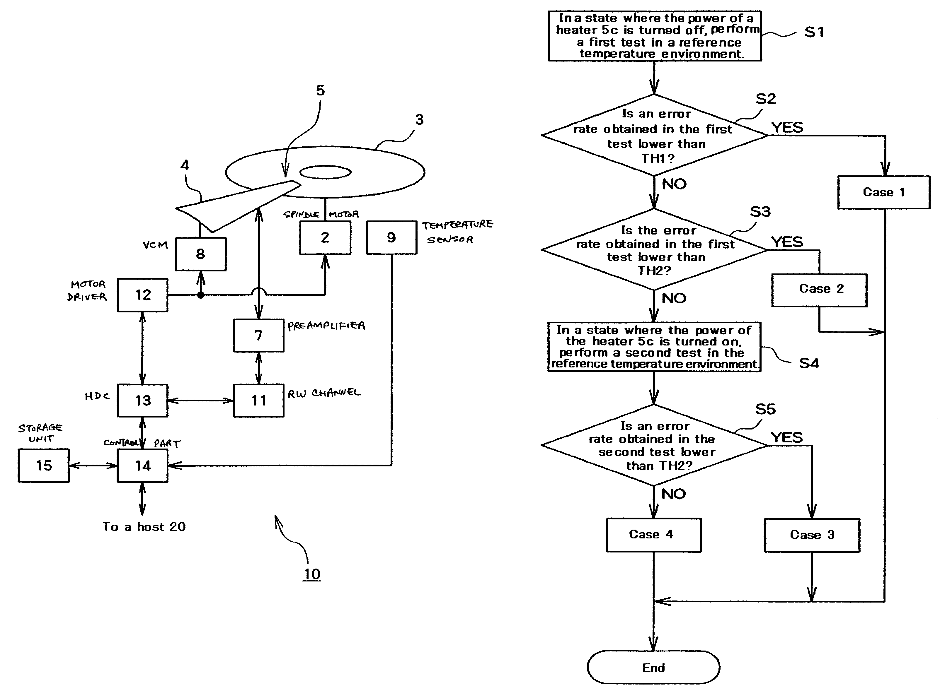
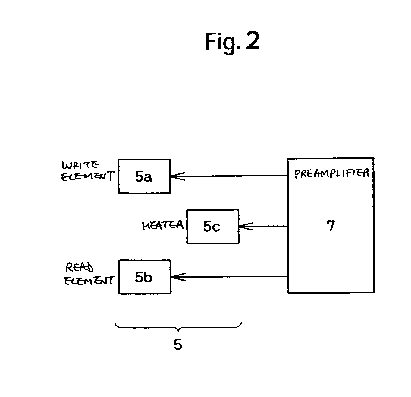
Embodiment of the invention improve the productivity of a magnetic disk drive that controls the flying height of a magnetic head by use of a heater. According to an embodiment, in a method for manufacturing a magnetic disk drive that writes / reads information to / from a magnetic disk medium by use of a magnetic head including a heater adapted to control the flying height, the read and write performance of the magnetic head is tested; a heating condition used at the time of heating by the heater is determined on the basis of the test results; and a control parameter that specifies the amount of heating by the heater in the determined heating condition is determined.

Description

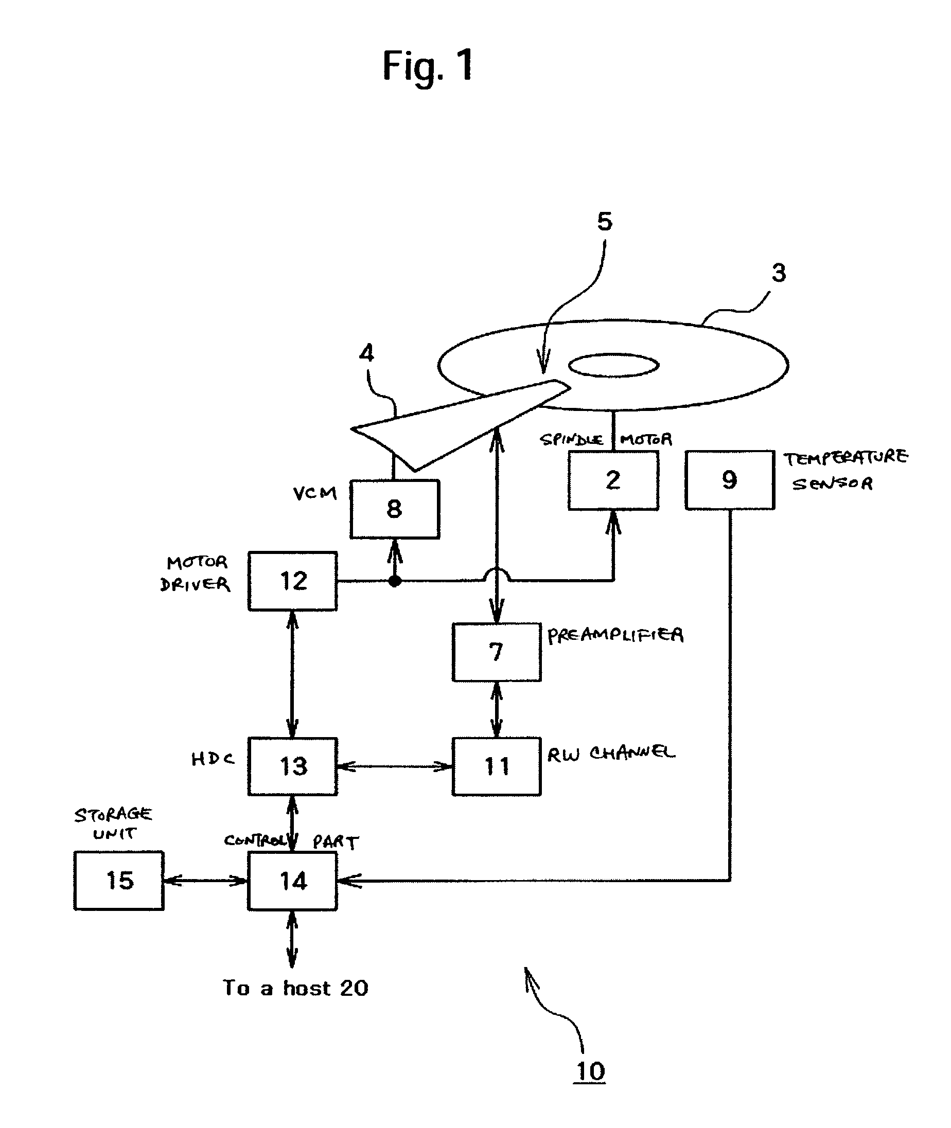
CROSS-REFERENCES TO RELATED APPLICATIONS[0001]This application claims priority from Japanese Patent Application No. JP2005-227298, filed Aug. 4, 2005, the entire disclosure of which is incorporated herein by reference.BACKGROUND OF THE INVENTION[0002]The present invention relates to a method for manufacturing a magnetic disk drive in which a magnetic head is heated by a heater to control the flying height from a magnetic disk medium to the magnetic head so that write performance and read performance are improved.[0003]In recent years, magnetic disk drives such as hard disks have achieved widespread use not only for computer equipment but also for home electric appliances such as hard disk recorders. Each of such magnetic disk drives comprises a magnetic disk medium and a magnetic head. The magnetic head magnetizes the magnetic disk medium while flying above it, and also reads a magnetized state of the magnetic disk medium, thus writing and reading information thereto and therefrom. ...

Claims


Application Information

Patent Timeline
Patent Type & Authority Patents(United States)
IPC IPC(8): G11B21/02
CPCG11B5/6005G11B5/6064G11B2005/0021
Inventor HIROYUKI, ONOSUK, MIKETANAKA, HIDEAKIKURITA, MASAYUKI
Owner HITACHI GLOBAL STORAGE TECH NETHERLANDS BV
Learn More