
Wireless repeater and method for managing air interface communications

a repeater and air interface technology, applied in the field of wireless communications, can solve the problems of reducing the overall the coverage gap between cells, and the capacity of the base station

Active Publication Date: 2009-01-20
SPRINT SPECTRUM LLC
View PDF55 Cites 114 Cited by
  • Summary
  • Abstract
  • Description
  • Claims
  • Application Information

AI Technical Summary

Benefits of technology

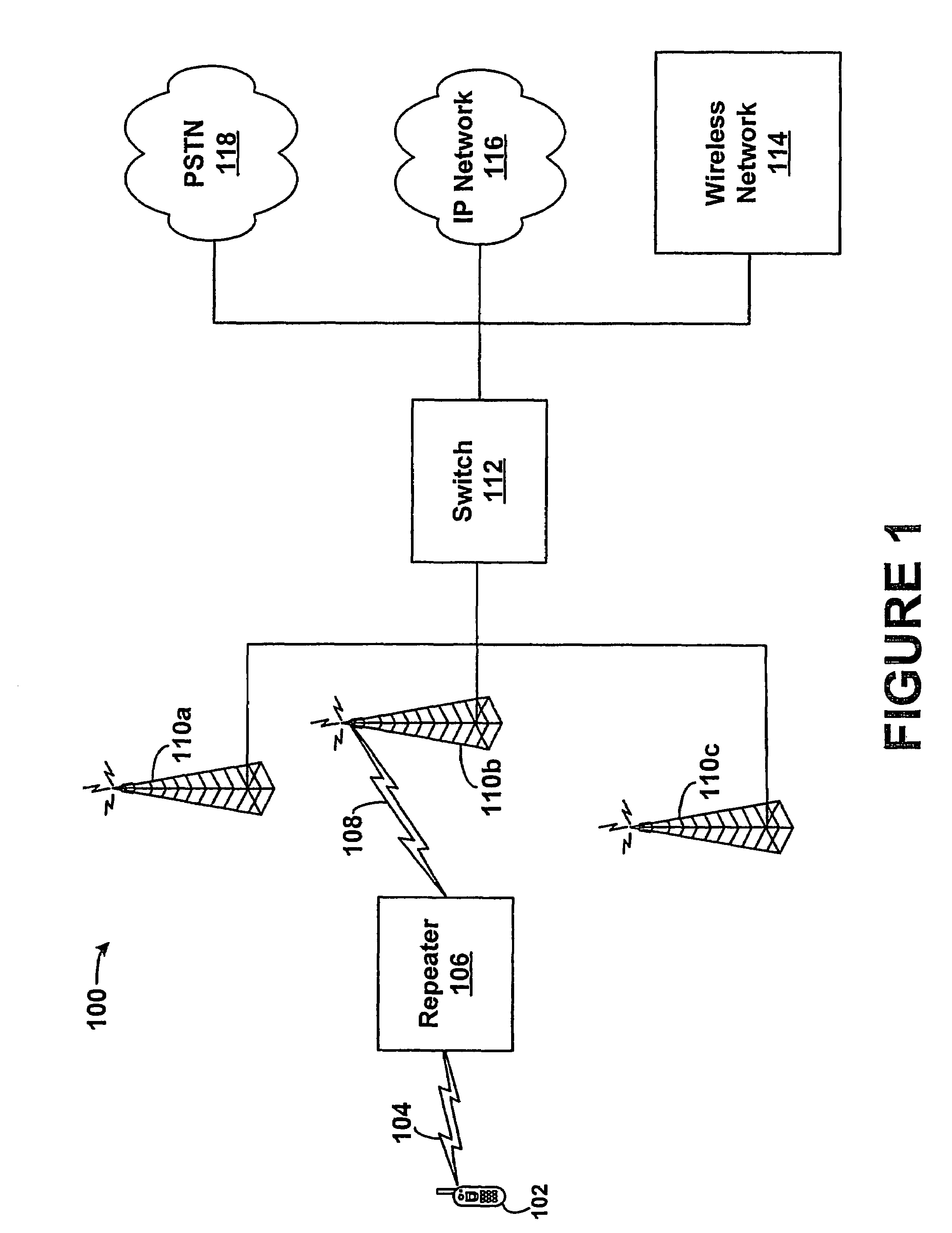
[0007]The present invention is directed to a wireless repeater and method for managing air interface communications. As described further below, a wireless repeater will communicate with a radio access network on multiple air interface beams, each having a forward link and a reverse link. In operation, the repeater will pass along to the mobile station substantially all of the forward link communications that the r

Problems solved by technology

Unfortunately, in some wireless networks, the cells may not seamlessly cover an entire area, so there may be a hole in coverage between cells.
However, radiating the amplified reverse link signals to all nearby base stations can decrease the capacity of base stations that are not the intended recipient of the amplified signals by increasing the ambient noise level.
Furthermore, even if the donor antenna of the repeater is set to radiate reverse link signals to a single base station, when that base station becomes loaded with primary traffic from the system (e.g., traffic not from the extended coverage of the repeater) the repeater traffic can cause a decrease in the overall capacity of the base station due to the noise rise at the base station caused by the noise generated by the repeater.

Method used


Image

  • Wireless repeater and method for managing air interface communications
  • Wireless repeater and method for managing air interface communications
  • Wireless repeater and method for managing air interface communications

Examples


Embodiment Construction

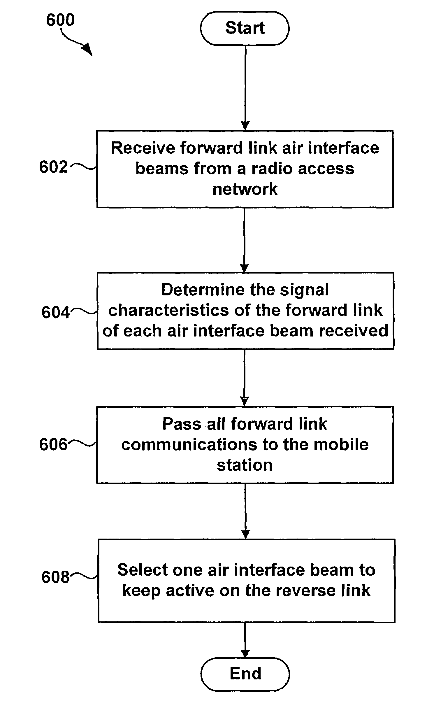
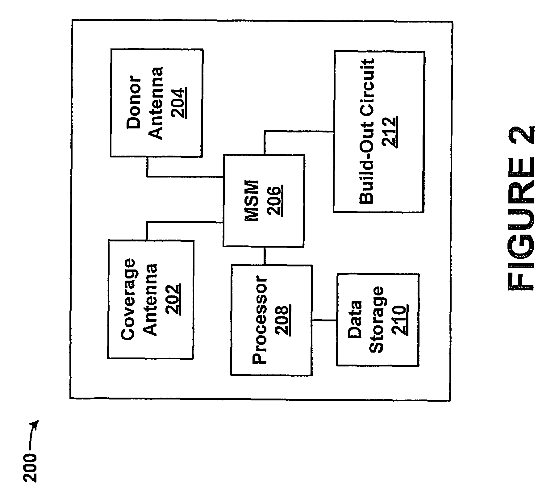
[0022]The exemplary embodiment of the present invention minimizes the number of reverse link air interface beams that a repeater keeps active. In this manner, the repeater may direct its retransmission of reverse link communications to a selected area, e.g., to a selected sector of a base station. According to the exemplary embodiment, a donor antenna of a repeater may be a smart antenna such as a phased array (PA) antenna that can dynamically (e.g., automatically in real time) point a narrow beam in a desired direction (e.g., by changing the phases of its various elements). The repeater may then include a coverage antenna, a mobile station modem (MSM), a processor and data storage. Preferably, the coverage antenna, MSM, PA, processor and data storage will be coupled together through a system bus or some other mechanism.

[0023]In an exemplary operation, the PA antenna will communicate with a radio access network on a plurality of air interface beams over an air interface between the ...


PUM


Abstract

A wireless repeater and method for managing air interface communications is provided. A repeater may include a donor antenna, a coverage antenna, a mobile station modem, a processor, and data storage. The donor antenna will receive a plurality of air interface beams on the forward link from a radio access network. The coverage antenna will pass each forward link beam received to a mobile station being served by the repeater. Further, the donor antenna will pass each forward link air interface beam to the MSM, where the MSM will apply a rake receiver to identify a signal characteristic of the forward link of each beam received, and the processor will record in the data storage the signal characteristic corresponding to each beam. Given this data, the repeater will select an air interface beam with the most preferable signal characteristic, and will keep only this beam active for reverse link communications.

Description

CROSS-REFERENCE TO RELATED APPLICATION[0001]This application is a continuation-in-part of U.S. application Ser. No. 10 / 659,647, filed Sep. 10, 2003.FIELD OF INVENTION[0002]The present invention relates to wireless communications, and more particularly, to wireless repeater functionality.BACKGROUND[0003]In a cellular wireless communication system, such as a code division multiple access (CDMA) system for instance, base stations are positioned throughout a coverage area and emit radio frequency radiation patterns that define cells. Mobile stations operating in a given cell may then wirelessly communicate with the serving base station, and the base station may provide connectivity with further network components such as switches and gateways that connect with transport networks.[0004]In a CDMA system, each cell is typically divided into a number of sectors, each of which is identified by a specific pseudo-noise offset (i.e., “PN offset”) of a specific spreading sequence that is used to...

Claims


Application Information

Patent Timeline
IPC IPC(8): H04B3/36
CPCH04B7/1555
Inventor OH, DAE-SIKYARKOSKY, MARK L.ASIF, SAAD Z.
Owner SPRINT SPECTRUM LLC
Learn More