Device for artificial respiration with an endotracheal tube

a technology of endotracheal tube and endotracheal tube, which is applied in the direction of tracheal tube, valve details, medical science, etc., can solve the problems of only being able to monitor the properties of the tube, the monitoring cannot discriminate or associate the mechanical properties of the structure beyond the y connection piece, and the patient is a danger to the patient, so as to avoid a disadvantageous increase in flow resistance and reduce the effect of expiration

Inactive Publication Date: 2009-01-27
REISSMANN HAJO
View PDF25 Cites 67 Cited by
  • Summary
  • Abstract
  • Description
  • Claims
  • Application Information

AI Technical Summary

Benefits of technology

[0042]Pressure-regulated ventilation via the double-lumen endotracheal tube may re readily continued under a suction with no positive or negative pressures occurring because the ventilation pressure is regulated just in the place where suction also makes itself felt, i.e. in the trachea. The means for pressure regulation is connected to the pressometers and controls the stream of gas. The ventilation pressure can further be controlled by a valve at the end distal to the patient of the lumen for expiration. The control of the pressure via the stream of gas presupposes that the inspiratory limb of the device, i.e. the hose and the lumen via which the stream of gas is fed for ventilation, does not exert too much resistance to the flow to prevent the ventilation device from building up the desired pressure in the trachea. Introduction of the suction catheter into the lumen through which the expiratory air is discharged avoids a disadvantageous increase in flow resistance in the other lumen.
[0043]It is preferred to additionally design the lumen for the expired stream of gas with a larger cross-section than has the lumen for the stream of gas für ventilation (asymmetric double-lumen endotracheal tube). The arrangement of the suction catheter could result in a reduction of expiration; however, this effect is alleviated or eliminated by the suction stream of gas which also causes some sort of expiration (passing by the ventilator). The pressure range predetermined by the user is not exited at any time in any case. For the first time, this allows to carry out a ventilation therapy during which the pressure never drops below the predetermined CPAP or PEEP (see above), even in connection with suction manoeuvres.

Problems solved by technology

This can cause a hazard to the patient because it will impede its ventilation and / or high pressures will build up in the lungs (with restriction being preponderant to expiration).
However, such monitoring cannot discriminate or associate the mechanical properties of the structures beyond the Y connection piece (filter, endotracheal tube, airways, lungs, surrounding tissue, muscle activity).
Therefore, monitoring the tube properties is only possible to a very limited extent and only major changes are detected, if at all.
Another problem is posed by the necessity for constant humidification of the patient's inspiration air because the endotracheal tube keeps it away from the natural humidifiers (the mucosae of the nose and pharynx).
Therefore, they cannot be employed for double-lumen endotracheal tubes.
Another problem is how to remove secretions and foreign matter from the endotracheal tube.
This interrupts ventilation and any continuously positive airway pressure (CPAP) or positive end-expiratory pressure (PEEP), which is a common prophylaxis against the collapse of diseased parts of the lung, cannot be maintained.
However, problems will arise by the fact that the portion of the lumen that is responsible for ventilation is reduced in dependence on the dimensions of the endotracheal tube and suction catheter and, as a consequence, its resistance to both inspiration and expiration air is more or less increased.

Method used


Image

  • Device for artificial respiration with an endotracheal tube
  • Device for artificial respiration with an endotracheal tube
  • Device for artificial respiration with an endotracheal tube

Examples


Embodiment Construction

[0053]While this invention may be embodied in many different forms, there are described in detail herein a specific preferred embodiment of the invention. This description is an exemplification of the principles of the invention and is not intended to limit the invention to the particular embodiment illustrated.

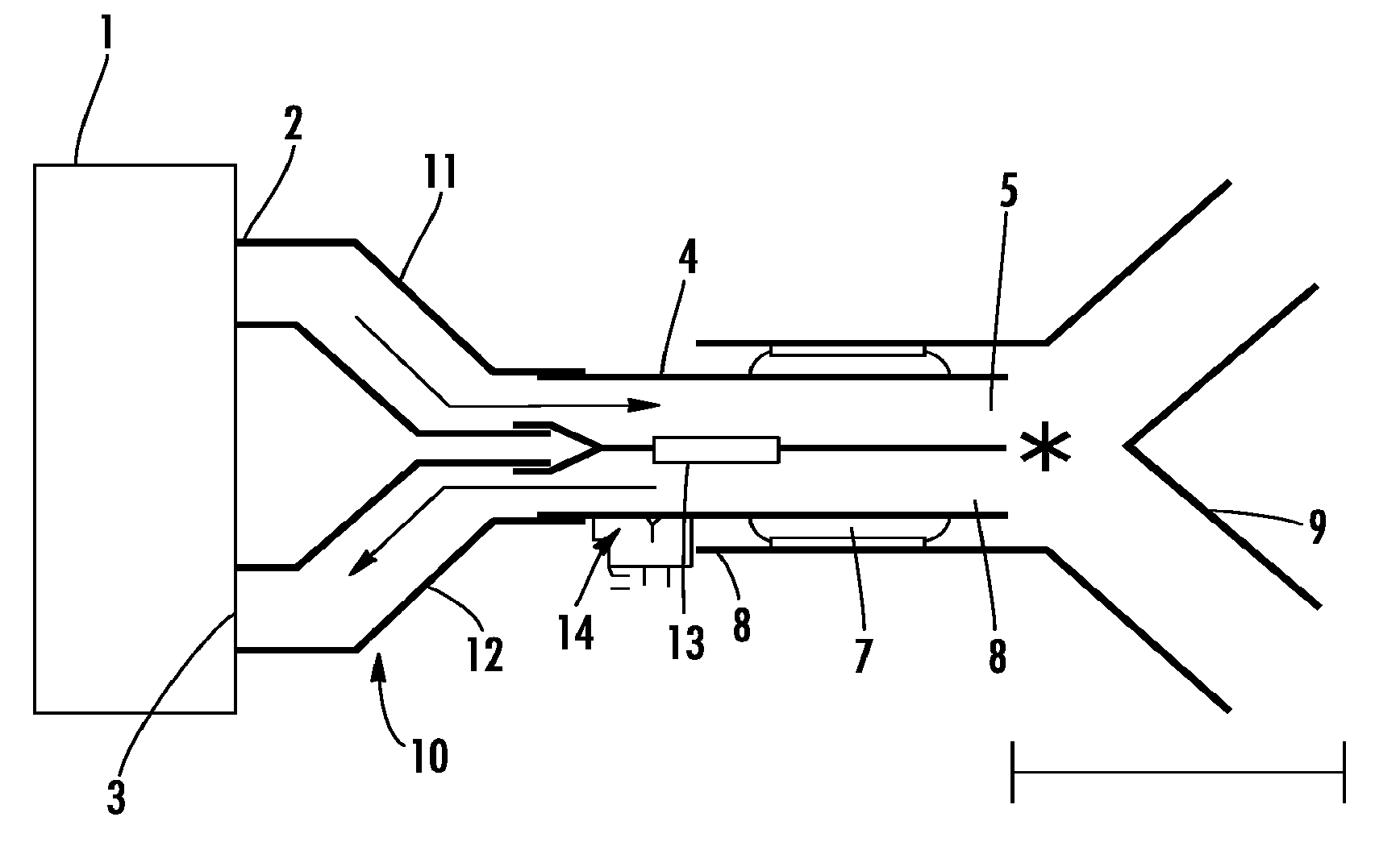
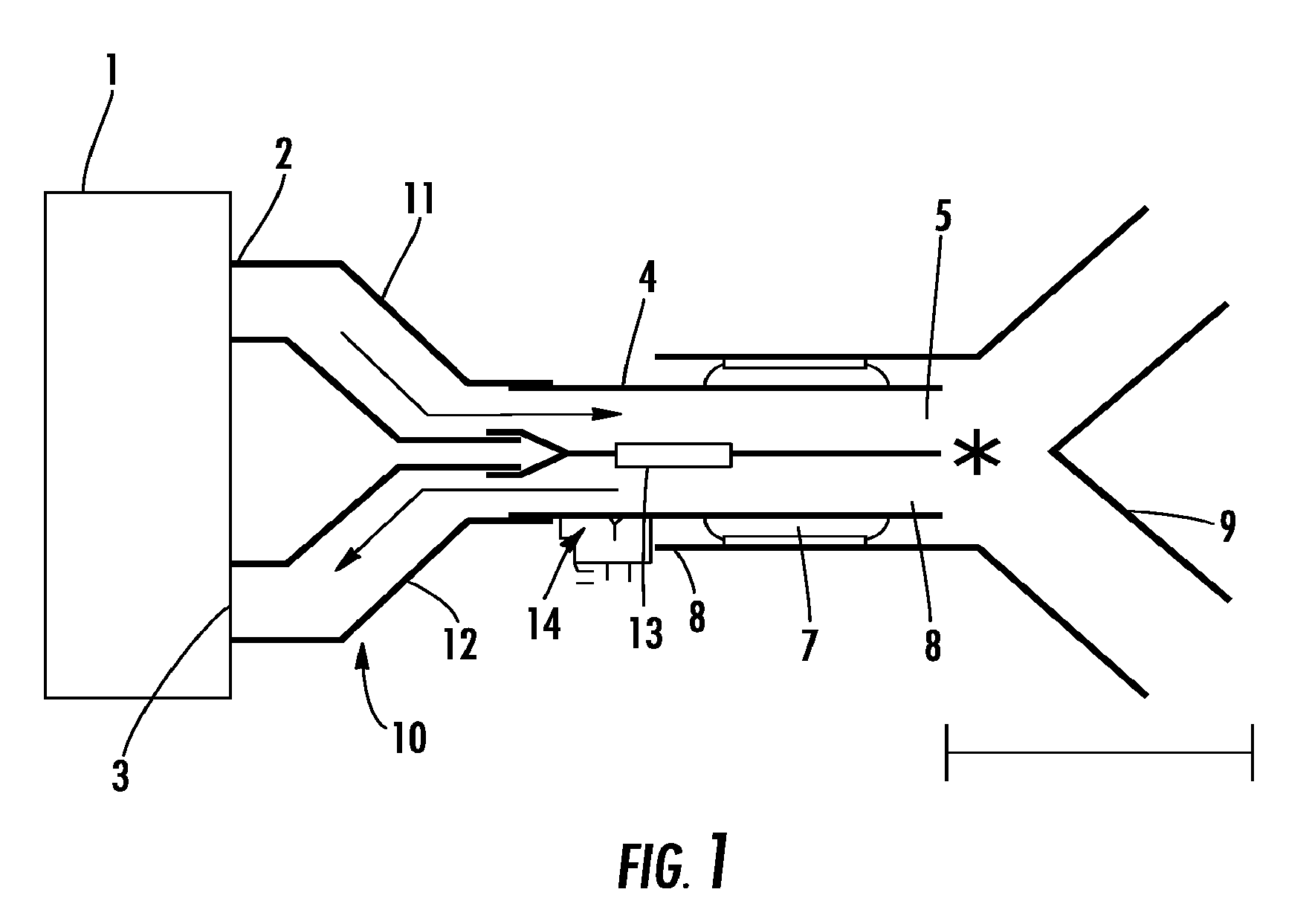
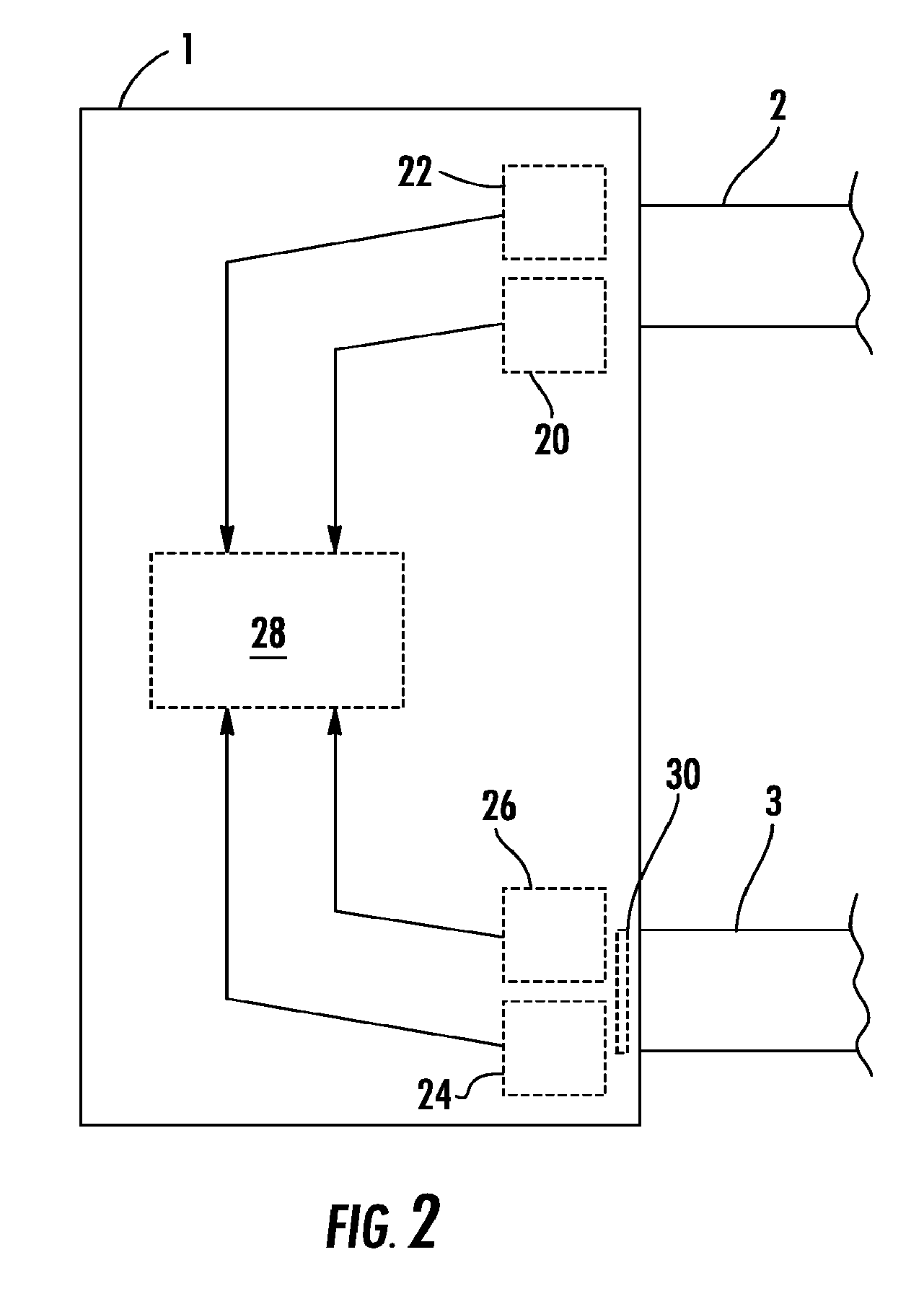
[0054]The device for ventilation comprises a ventilator 1 with an outlet 2 at which a stream of gas is provided and an inlet 3 to which a stream of expired gas can be fed. At the inlet 3, the ventilator 1 has an active valve which is closed during inspiration in order to maintain the pressure in the lungs, and which is opened during expiration. Behind the valve, the expired gas can be released to the environment. Alternatively, the stream of expired gas can be prepared for reuse in the ventilator 1 (by removing the CO2) and the gas needed for ventilation will be re-supplied to the outlet where fresh ventilation gas can be admixed.

[0055]Further, there is an endotracheal tube 4...


PUM


Abstract

A device for ventilation, comprising
    • a ventilator for providing a stream of gas for ventilation at an outlet,
    • a hose for inspiration air one end of which is connected to the outlet,
    • a double-lumen endotracheal tube one lumen of which, at its end distal to the patient, is connected to the other end of the hose for inspiration air,
    • flow meters for measuring the streams of gas in the two lumina of the endotracheal tube,
    • pressometers for measuring the pressures at the ends distal to the patient of the two lumina,
    • an evaluation means for determining the flow resistance in a lumen flowed through by gas because of the stream of gas measured therein and the pressures measured, and
    • a means for outputting an information about the flow resistance of the lumina.

Description

CROSS-REFERENCE TO RELATED APPLICATIONS[0001]Not ApplicableSTATEMENT REGARDING FEDERALLY SPONSORED RESEARCH[0002]Not ApplicableBACKGROUND OF THE INVENTION[0003]The invention relates to a device for ventilation via an endotracheal tube.[0004]The predominant majority of patients being ventilated during an intensive-care therapy or anaesthesia have their airway secured by an endotracheal tube. To this end, an endotracheal tube which consists of a plastic or rubber tube, as a rule, is introduced into the trachea through the mouth or nose or by a making an incision in the trachea (“tracheotomy”). At the tracheal end, the endotracheal tube mostly is provided with a inflatable endotracheal tube “cuff” which seals the trachea, permits ventilation at an excess pressure, and protects the airways from the penetration of foreign matter. The end distal to the patient of the endotracheal tube is coupled to a ventilation device via a hose system. At the point of transition from the endotracheal tu...

Claims


Application Information

Patent Timeline
Patent Type & Authority Patents(United States)
IPC IPC(8): A61M16/00A61M16/04
CPCA61M16/00A61M16/04A61M16/0486A61M16/0096A61M16/0463A61M2016/0027A61M2016/0039A61M2016/0042A61M16/1045Y10S128/912Y10S128/911A61M16/042A61M16/024
Inventor REISSMANN, HAJO
Owner REISSMANN HAJO
Why Eureka
Try Eureka