
Implantable counterpulsation cardiac assist device

Inactive Publication Date: 2009-01-27
PPTT
View PDF47 Cites 1 Cited by
  • Summary
  • Abstract
  • Description
  • Claims
  • Application Information

AI Technical Summary

Benefits of technology

[0021]It is still another object of the present invention to provide an implantable counterpulsation cardiac assist device which increases coronary blood flow.

Problems solved by technology

However, with each such event, the heart muscle is further injured and the resulting scar tissue decreases the ability of the left ventricle to perfuse the body.
The result is that the work of the heart is decreased during systole.

Method used


Image

  • Implantable counterpulsation cardiac assist device
  • Implantable counterpulsation cardiac assist device
  • Implantable counterpulsation cardiac assist device

Examples


Embodiment Construction

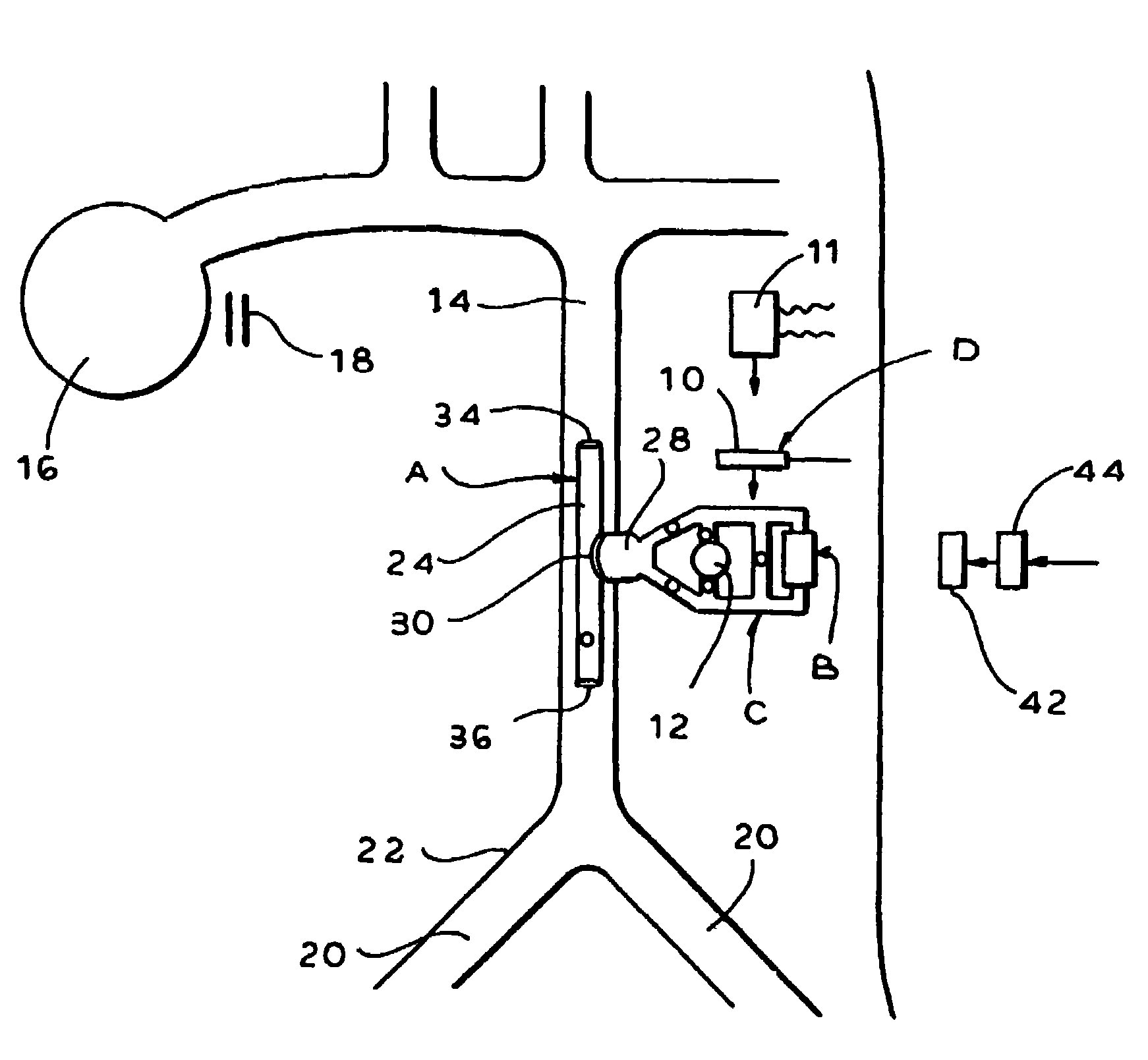
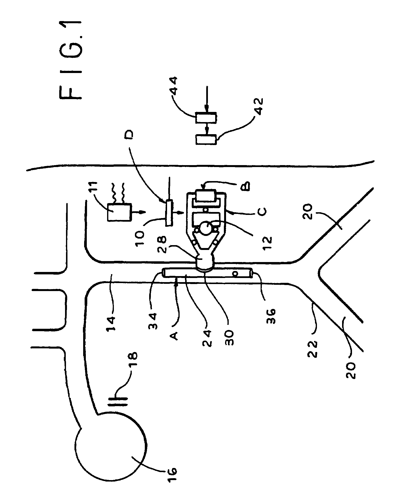
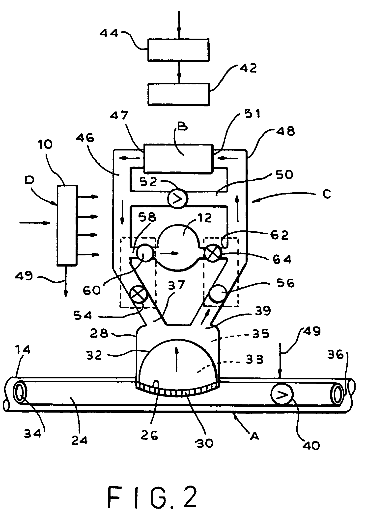
[0044]As seen in FIG. 1, the implantable counterpulsation cardiac assist device of the present invention includes a hollow tubular element with a unidirectional pressure sensitive valve, and separate variable volume chambers, generally designated A, a sealed hydraulic pump unit, generally designated B, a closed hydraulic system including a multi-valve chamber, generally designated C, which operably connects element A and pump B, and valve control means, generally designated D, which controls the valves in chamber C in a way that converts the fluid flow from continuously operating pump B to intermittently pump blood, in, a counterpulsation mode, in synchronization with the operation of heart.

[0045]Valve controller 10 receives electrical output signals from an electrocardiograph (not shown) and controls the valves within chamber C in accordance with those signals. The electrocardiac signals are a function of the operation of the heart. Controller 10 may also receive output signals fro...


PUM


Abstract

A hollow tubular element is inserted in the descending aorta. The caudad end contains a pressure sensitive passive or preferably, hydraulically or electrically activated, unidirectional valve. A flexible diaphragm situated in a rigid shell affixed over an opening in the element wall divides the shell interior into first and second variable volume chambers. The first chamber opens to the artery. A continuously operating electrical pump is connected to the second chamber through a closed hydraulic system including a multi-valve chamber. The valves regulate fluid flow to the second chamber in accordance with electrical signals from the heart. Fluid flow is directed to the second chamber during cardiac diastole and away from the second chamber during cardiac systole, causing the device to function in a counterpulsation mode. The work of the heart is decreased and coronary blood flow is increased to promote the formation of new coronary collateral channels and the perfusion of the heart itself. In the event of mechanical failure, pre-implantation heart function is not impeded.

Description

CROSS-REFERENCE TO RELATED APPLICATIONS[0001]The present application is a divisional of application Ser. No. 09 / 536,789 filed Mar. 28, 2000 now U.S. Pat. No. 6,770,024, the entire content of which is incorporated herein by reference.BACKGROUND OF THE INVENTION[0002]The present invention relates to a cardiac assist device and more particularly to an implantable artificial left ventricle including a continuously operating pump and hydraulic valve system which assists the heart by intermittently pumping blood in synchronization with operation of the heart.[0003]Congestive heart failure represents an enormous national public health concern, with a prevalence of 4.9 million cases and an incidence of more than 400,000 cases a year. Some 50,000 people a year die of heart failure and it is a contributing factor in 250,000 additional deaths a year.[0004]Congestive heart failure accounts for more than 800,000 hospitalizations a year, at a hospital cost of $18.8 billion. The direct and indirec...

Claims


Application Information

Patent Timeline
IPC IPC(8): A61M1/12A61M60/178A61M60/268A61M60/427A61M60/873A61M60/892A61M60/894
CPCA61M1/106A61M1/107A61M1/1065A61M2205/8243Y10T137/7885Y10T137/0491Y10T137/7883A61M60/435A61M60/274A61M60/892A61M60/148A61M60/427A61M60/178A61M60/894A61M60/873F16K15/1471
Inventor RASTEGAR, JAHANGIR S.SOROFF, HARRY
Owner PPTT
Learn More