Directional lamp daytime running light module and vehicular turn signal control system

a turn signal control system and daytime running light technology, applied in the direction of manufacturing tools, welding apparatus, transportation and packaging, etc., can solve the problems of reducing the chance of being in a multi-vehicle accident, half of all multi-vehicle accidents occur, not required or practical, etc., to achieve high efficiency and comparative fuel economy savings

Inactive Publication Date: 2009-01-27
KESTERSON RAYMOND
View PDF30 Cites 18 Cited by
  • Summary
  • Abstract
  • Description
  • Claims
  • Application Information

AI Technical Summary

Benefits of technology

[0014]The present invention provides a daytime running light module for controlling the illumination of conventional domestic and imported vehicle directional turn signal lamps, primarily in the front of a vehicle, and not only limited to conventional incandescent turn signal bulb / lamp assemblies, but also including right-hand and left-hand vehicular light emitting diode (LED) turn signal lamps, or turn signal lamps consisting of two or more individual LEDs arrayed in such a fashion as to form a unified turn signal LED lamp assembly or unit. The daytime running light module / system includes a pair of single pole switches that are to be interconnected between the vehicular directional lights and a power source to control the light emitted from the directional lights of the vehicle. That is, the module operates to control pairs of bulbs when the brightest filament of a two-filament signal bulb or the bright filament of one filament signal bulb system is illuminated, so that the brighter filaments or bulbs will be illuminated when the operator wishes to draw attention to the vehicle for safety purposes. The module automatically controls the light output of the turn signal bulbs. This DRL lighting is to be turned off automatically by the vehicle's main headlight switch, when the main vehicular headlight switch is actuated into either one of its two vehicular illumination modes, namely the parking light position or the headlight plus parking light position. Because any U.S. vehicle's front directional lamps are expectedly amber in output, as required by law, employment of such bulbs as daytime running lights yields a distinctive high intensity amber output that is more noticeable than white output DRLs in a white daylight-flushed world. The present invention is designed to allow the vehicle's internal turn signal bulb-failure indication system to monitor these same bulbs for bulb failure due to burn out. These same directional lamp bulbs are highly efficient, allowing the present invention to offer comparative fuel economy savings over that of the more common headlight driven DRL systems. Compared to a vehicle with its headlights on, the present invention is very frugal with respect to electrical current consumption, and is the most electrically conservative when compared to this author's previous designs. This design employs a dynamic safety reconnect feature which reconnects factory signal wiring with factory signal bulbs instantaneously with any hazard lighting or signaling activation, and such is a failsafe that is designed into the module at the module's most basic operational level. The present invention also has multiple motorcycle applications as a turn signal control system, front and rear, making the motorcycles safer by making them more visible on the roadways during both driving and stopping conditions.

Problems solved by technology

This type of collision avoidance system further reduces the chances of being in a multi-vehicle accident at dusk, dawn, and on overcast days—times when environmental visibility is low.
Some sources estimate that just under half of all multi-vehicle accidents occur because of perception and recognition errors.
Such bulb failure indication is deemed as essential feedback to the vehicle operator, but is not required or practical on vehicles that tow trailers or other vehicles.
From an engineering standpoint, energy is not free for such safety lighting, and does not come from the vehicle battery, as many people believe.
There is concern in the automotive world that motorcycles are at an ever-increasing disadvantage on the roadway, as more and more automobiles gain ‘white light output’ headlight-driven DRL systems.

Method used


Image

  • Directional lamp daytime running light module and vehicular turn signal control system
  • Directional lamp daytime running light module and vehicular turn signal control system
  • Directional lamp daytime running light module and vehicular turn signal control system

Examples


Embodiment Construction

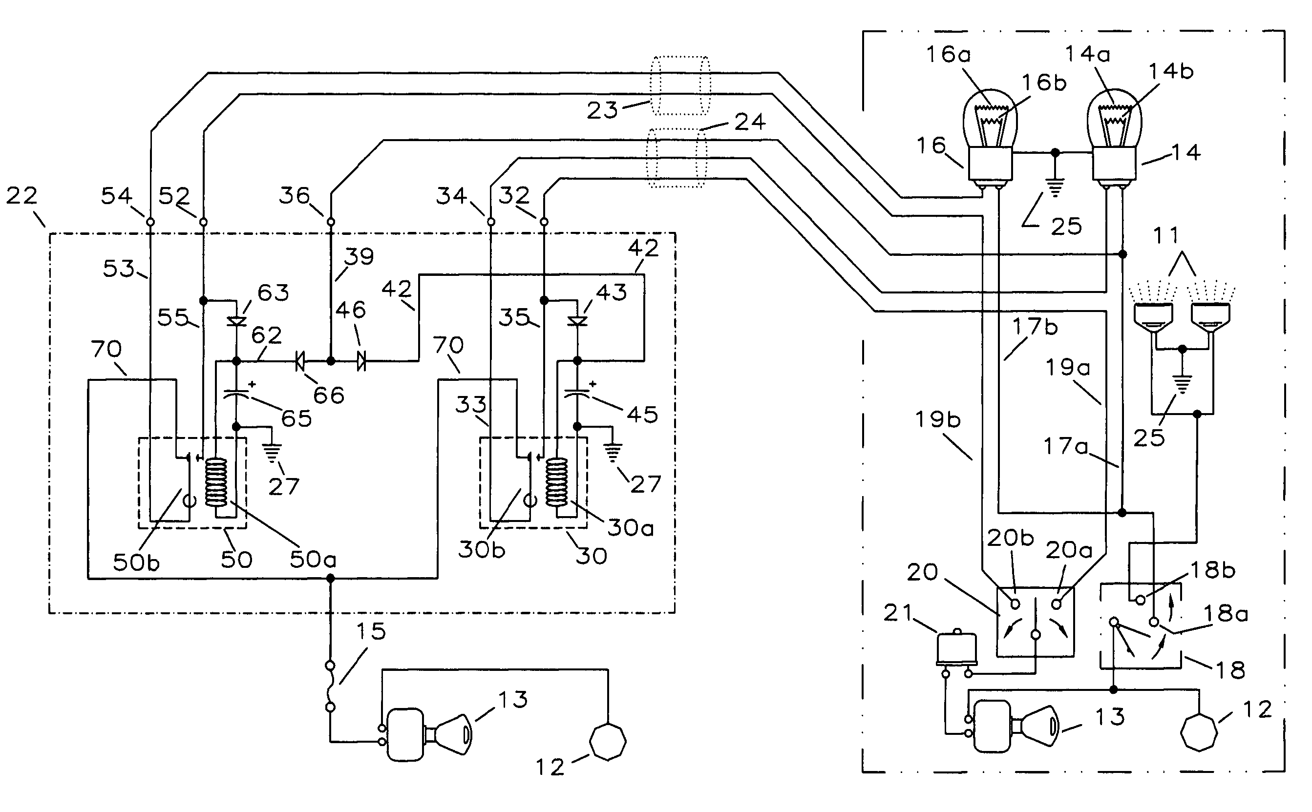
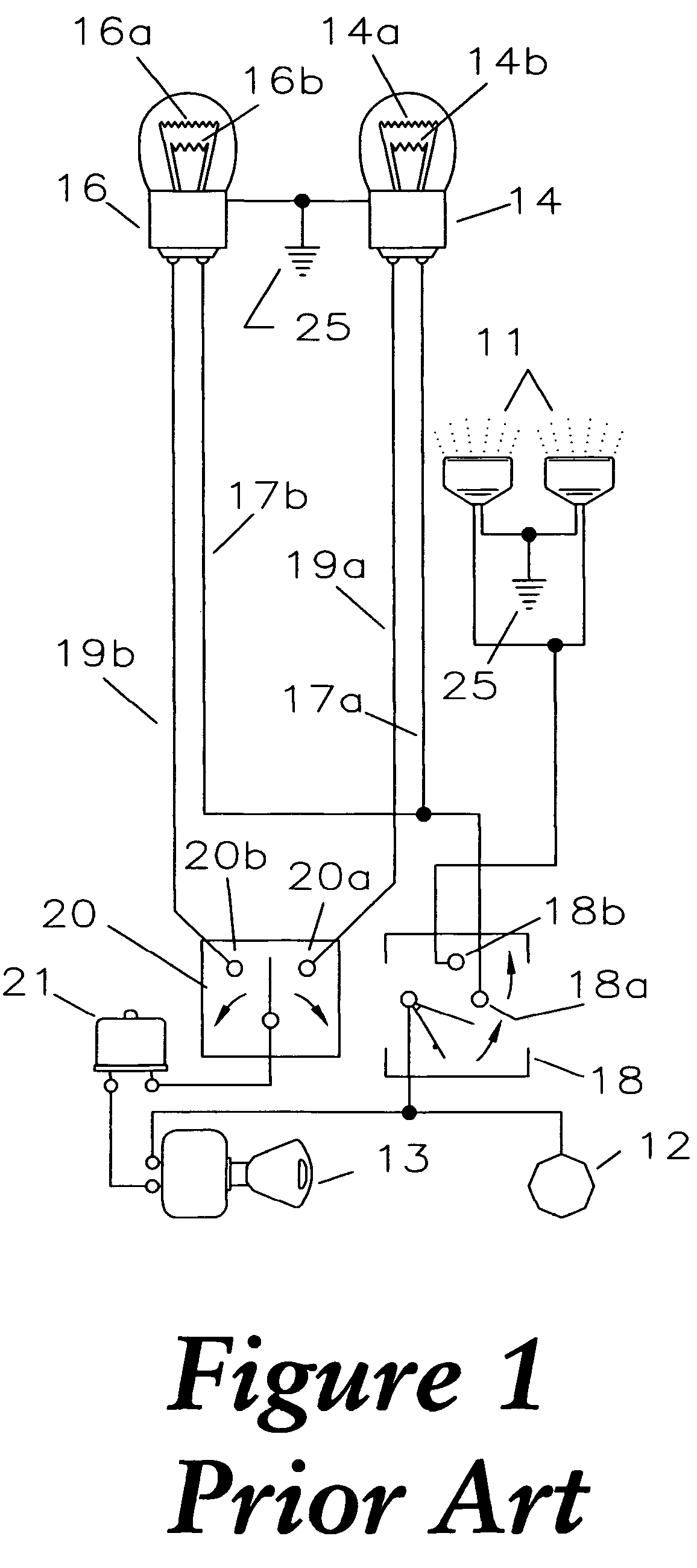
[0022]Referring now to FIG. 1, a conventional connection between a power source 12 and sets of automotive lights 11, 14, and 16 commonly found in most typical motor vehicles is illustrated. The power source 12 is a conventional vehicular power source, such as a 12-volt battery. The set of lights includes one pair of headlights 11, and a pair of front vehicular signal lights 14, 16 having dual filament bulbs. Traditional domestic and many newer import vehicle designs include a pair of front dual filament vehicular signal lights 14, 16 that are considered the front parking / turning lights. These front vehicular signal lights 14, 16 are typically integrated into the vehicle generally at the front right corner and the front left corner of the vehicle. The position of the front vehicular signal lights 14, 16 allow the operator to provide visible signals in traffic to other vehicles in close proximity to same vehicle concerning the operator's directional intentions in operation of that veh...


PUM

PropertyMeasurementUnit
light intensityaaaaaaaaaa
electrical currentaaaaaaaaaa
voltageaaaaaaaaaa

Abstract

A vehicular lighting control system for controlling the illumination of a vehicle's external directional / turn signaling and / or hazard lighting, by controlling continuous illumination of pairs of the brightest filaments of single or dual filament bulb designed vehicles. The system controls to operate the brightest filaments when the operator wishes to draw attention to the vehicle for safety, or for visibility purposes, without the same system negatively affecting normal operation of existing turn signal / hazard warning systems. The system automatically and manually controls the light output as desired by the vehicle operator, incorporates the vehicle's internal turn signal bulb-failure indication subsystem to continuously monitor the target bulbs for any failure event, and employs a dynamic safety reconnect feature, an attribute which reconnects factory wiring with factory bulbs instantaneously with any signaling or hazards activation. The device employs a zero-system current drain, actual dual bulb activation / current consumption notwithstanding, for minimum environmental impact / maximum fuel conservation.

Description

CROSS REFERENCE TO RELATED PATENT APPLICATIONS[0001]This non-provisional patent application is a continuation-in-part of co-pending patent application Ser. No. 10 / 690,044, which was filed on Oct. 21, 2003 and issued on Mar. 28, 2006 as U.S. Pat. No. 7,019,463, and claims priority from and is a continuation-in-part of PCT application Ser. No. PCT / US04 / 34535, which was filed on Oct. 20, 2004 and designated the United States, each of which are relied upon and incorporated herein by reference.FIELD OF THE INVENTION[0002]The present invention is a multiple application device that relates to automotive directional lamp arrangements, more commonly known as turn signal lamps, and more particularly to a module / system for generating high-intensity daytime running lights (DRLs) on a vehicle utilizing existing front directional / turn signal lamps, yet still retaining a vehicle's internal turn signal bulb-failure detection system, when present. Additionally, the utilization of this device in rear...

Claims


Application Information

Patent Timeline
Patent Type & Authority Patents(United States)
IPC IPC(8): B60Q1/02
CPCB60Q1/2603B60Q1/28B60Q1/38B60Q11/007B60Q2400/30
Inventor KESTERSON, RAYMOND
Owner KESTERSON RAYMOND
Why Eureka
Try Eureka