Method and apparatus for determining the rotor position of an electric motor from the electric current and the angular acceleration

a technology of electric current and angular acceleration, applied in the direction of motor/generator/converter stopper, dynamo-electric converter control, instruments, etc., can solve the problems of insignificant hardware complexity of the absolute measurement system but also the incremental measurement system, and the magnitude of the amplitude of the movement which is excited by the known signal that is applied often represents a disadvantage, so as to increase the accuracy of the rotor position determination

Inactive Publication Date: 2009-01-27
SIEMENS AG
View PDF11 Cites 11 Cited by
  • Summary
  • Abstract
  • Description
  • Claims
  • Application Information

AI Technical Summary

Benefits of technology

[0007]Passing current through the stator in the form of square-wave pulses results in the advantage that the acceleration signal that is produced can be computationally evaluated easily. The duration of each square-wave pulse is long enough to produce an acceleration signal which can be associated with this pulse and can be evaluated unambiguously, while at the same time being sufficiently short that the rotor position does not change significantly during the pulse, in particular in cases in which the rotor is stationary at the start of the position-determination process. A current-flow pattern is preferably formed from a plurality of square-wave pulses of different mathematical sign, and results in no change in the position of the rotor, or only a very small change in its position. In this case, separate acceleration measurements are carried out throughout the duration of at least one of the square-wave pulses, preferably throughout the entire duration of the current-flow pattern. A particularly small deflection of the rotor during the current-flow pulse is achieved by means of a pulse which has a central section of a first mathematical sign, directly preceded and followed by edge sections of the opposite mathematical sign. In particular, the parameters of a current-flow pulse such as this composed of three sections can be selected in a simple manner such that no permanent change in the angular position of the rotor is induced overall.
[0011]In principle, a single pulse pattern and thus a single pulse duration is sufficient to determine the angular position of the rotor. According to one advantageous development, which can be considered in particular for continuous rotor-position determination during motor operation, but also to increase the accuracy of the rotor position determination during starting of the motor, periodic repetition of the current flow through the stator windings with the pulse pattern is provided.

Problems solved by technology

However, depending inter alia on the motor geometry, not only an absolute measurement system but also an incremental measurement system can represent considerable hardware complexity.
On the other hand, in the case of the method according to DE 44 37 793 C2, the magnitude of the amplitude of the movement which is excited by the known signal that is applied often represents a disadvantage.

Method used


Image

  • Method and apparatus for determining the rotor position of an electric motor from the electric current and the angular acceleration
  • Method and apparatus for determining the rotor position of an electric motor from the electric current and the angular acceleration
  • Method and apparatus for determining the rotor position of an electric motor from the electric current and the angular acceleration

Examples


Embodiment Construction

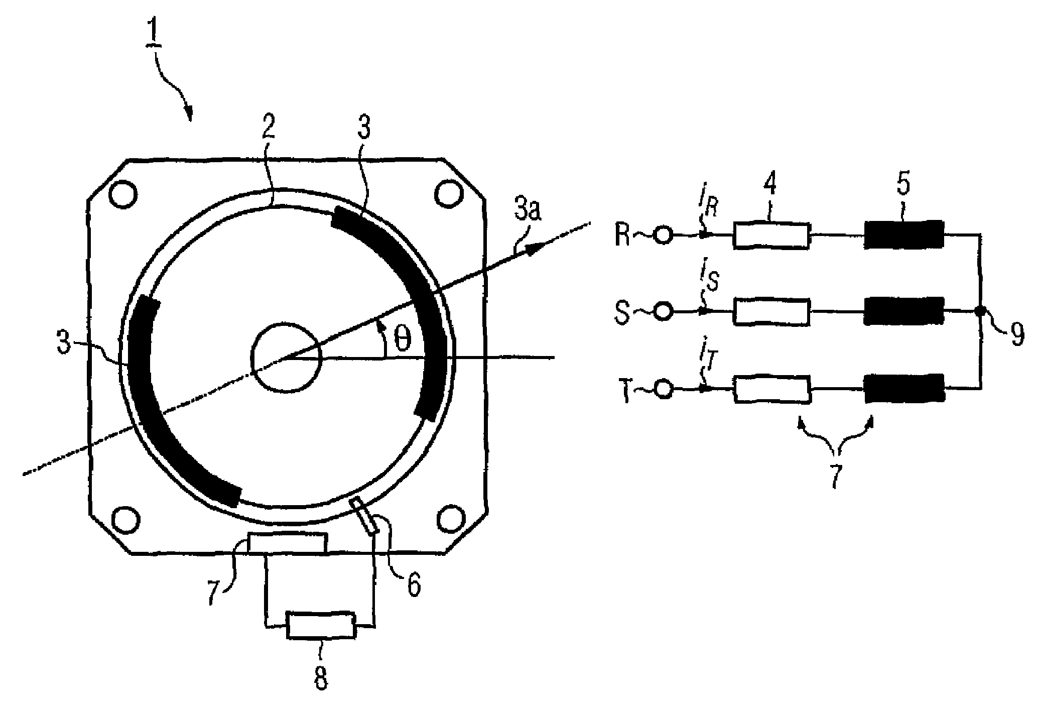
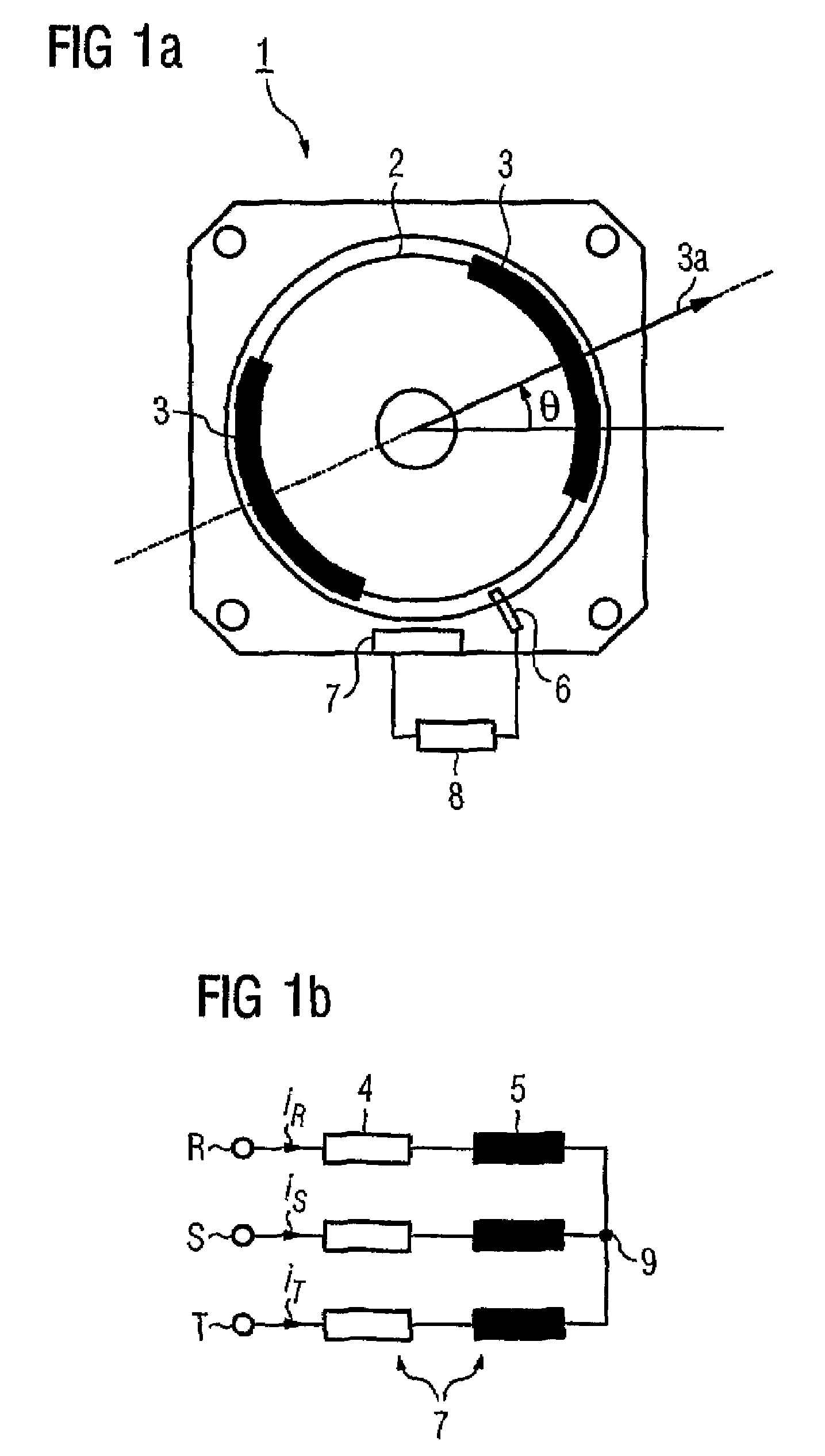
[0019]FIG. 1a shows the cross section through a two-pole synchronous motor 1 with permanent-magnet excitation, which is also referred to for short in the following text as a motor. The rotor 2 of the electric motor 1 has two permanent magnets 3 which, together, produce a field flux in the direction of the arrow 3a. The angle θ that is shown in FIG. 1a, where −π≦θ2. An acceleration sensor 6, preferably a Ferraris sensor, is provided in order to measure the angular acceleration α; that is to say the second derivative with respect to time of the rotor position. An evaluation unit 8 interacts with the acceleration sensor 6, which is indicated only schematically, and with the stator windings 7, which are likewise indicated only by way of example in FIG. 1a, and (as will be explained in more detail in the following text with reference to FIGS. 3 to 5) firstly produces defined current pulses in order to induce an angular acceleration α of the rotor 2, secondly calculates the signal coming ...


PUM


Abstract

The invention relates to a method for determining the angular position (theta) of a rotor (2) pertaining to an electric motor (1) and comprising a number of pairs of poles. Said method consists of the following steps: a pulse pattern (PM1,PM2,PM3) with a pulse duration (T) flows through at least one stator coil (7) of the electric motor (1), such that the rotor (2) does not rotate by more than 90 DEG, divided between the number of pairs of poles, during the pulse duration (T); the angular acceleration (alpha) of the rotor (2), caused by the pulse pattern flowing through the at least one stator coil, (7) is detected; and the angular position (theta) of the rotor (2) is determined by means of the correlation between the flow through the stator coil (7) and the angular acceleration (alpha) of the rotor (2).

Description

BACKGROUND OF THE INVENTION[0001]The invention relates to a method and an apparatus for determination of the rotor position of an electric motor, in particular of a brushless electric motor. A method for controlling an electric motor, in which the position of a rotor relative to a stator is determined, is known, for example, from DE 44 37 793 C2. Analogously to the terminology used in this document, the terms “rotor” and “stator” in the following text refer to the functional basic elements of an electric motor which assume a variable position (rotor) or a fixed position (stator) relative a fixed coordinate system. This therefore also covers linear motors as electric motors.[0002]In the method which is known from DE 44 37 793 C2, the relationship between a known signal which is applied to the electric motor and the movement of the rotor stimulated by this is used to determine the position of the rotor, in which case, by way of example, the change in the position of the rotor is measu...

Claims


Application Information

Patent Timeline
Patent Type & Authority Patents(United States)
IPC IPC(8): G01B7/30G01P3/488H02P6/16H02P6/18
CPCH02P6/16H02P6/185
Inventor FINKLER, ROLANDKOPKEN, HANS-GEORG
Owner SIEMENS AG
Why Eureka
Try Eureka