Antenna apparatus

a technology of antenna and antenna body, applied in the direction of resonant antenna, other accessories, radiating element structure forms, etc., can solve the problems of obstructing the original radiation pattern, limiting the operation of up to approximately several hundred megahertz of practically engineered oxide magnetic materials for high frequency, and making the effects of unexpected modes not negligible. , to achieve the effect of easy overlap

Inactive Publication Date: 2009-01-27
SONY CORP
View PDF10 Cites 32 Cited by
  • Summary
  • Abstract
  • Description
  • Claims
  • Application Information

AI Technical Summary

Benefits of technology

[0029]The present invention takes into consideration the fact that the dielectric property is also contained in the magnetic material used as an insulative material and degrades the effect of expanding the bandwidth. According to the embodiment of the present invention, an empty layer is inserted into insulative material layers. This ensures an effect of providing relative permittivity ∈r approximate to 1 for the entire intermediate layer between the radiating conductor and the reference conductor. It is preferable to configure the empty layer so that the permittivity becomes discontinuous in the electric flux direction and the permeability becomes continuous in the magnetic flux direction. In this case, the permittivity can be decreased by preventing a decrease in the permeability for the entire intermediate layer.
[0030]The insulative material layer can, comprise hexagonal ferrite. The hexagonal ferrite can be an oxide magnetic material including; a Y-type ferrite compound represented by general formula Ba2Me12Fe12O22; a Z-type ferrite compound represented by general formula Ba3Me12Fe24O41; or an M-type ferrite compound represented by general formula BaMe2xFe(12-x)O19. (In these formulas, Me1 is appropriately selected from one or more of Ni2+, Zn2+, Mn2+, Mg2+, Cu2+, Fe2+, and Co2+ to adjust composition. Me2 is appropriately selected from one or more of Al3+, Cr3+, Sc3+, and In3+ to adjust composition, or is a mixture of the same amount of (Ti4+, Sn4+, Zn4+) and Me1.) In order to maintain high permeability and low permittivity, the present invention adjusts compositions basically containing divalent metal ion or trivalent metal ion. This makes it possible to provide properties suitable for the magnetic-material microstrip patch antenna for microwave bands.
[0032]The present invention can provide an antenna apparatus excellent in the microstrip patch antenna construction provided by disposing a radiating conductor and a reference conductor opposite to each other using an intermediate including a magnetic material as insulative substance.

Problems solved by technology

When the magnetic material is used to construct the microstrip patch antenna, however, the bandwidth expands to cause a side effect of making effects from unexpected modes not negligible.
This is because the modes operate in a wide band and easily overlap with each other.
These components may obstruct an originally intended radiation pattern.
Presently, there is a limitation of up to approximately several hundreds megahertz of operations on practically engineered oxide magnetic materials for high frequencies.
In most cases, the high permeability cannot be expected in a region exceeding the frequency.

Method used


Image

  • Antenna apparatus
  • Antenna apparatus
  • Antenna apparatus

Examples


Embodiment Construction

[0043]Embodiments of the present invention will be described in further detail with reference to the accompanying drawings.

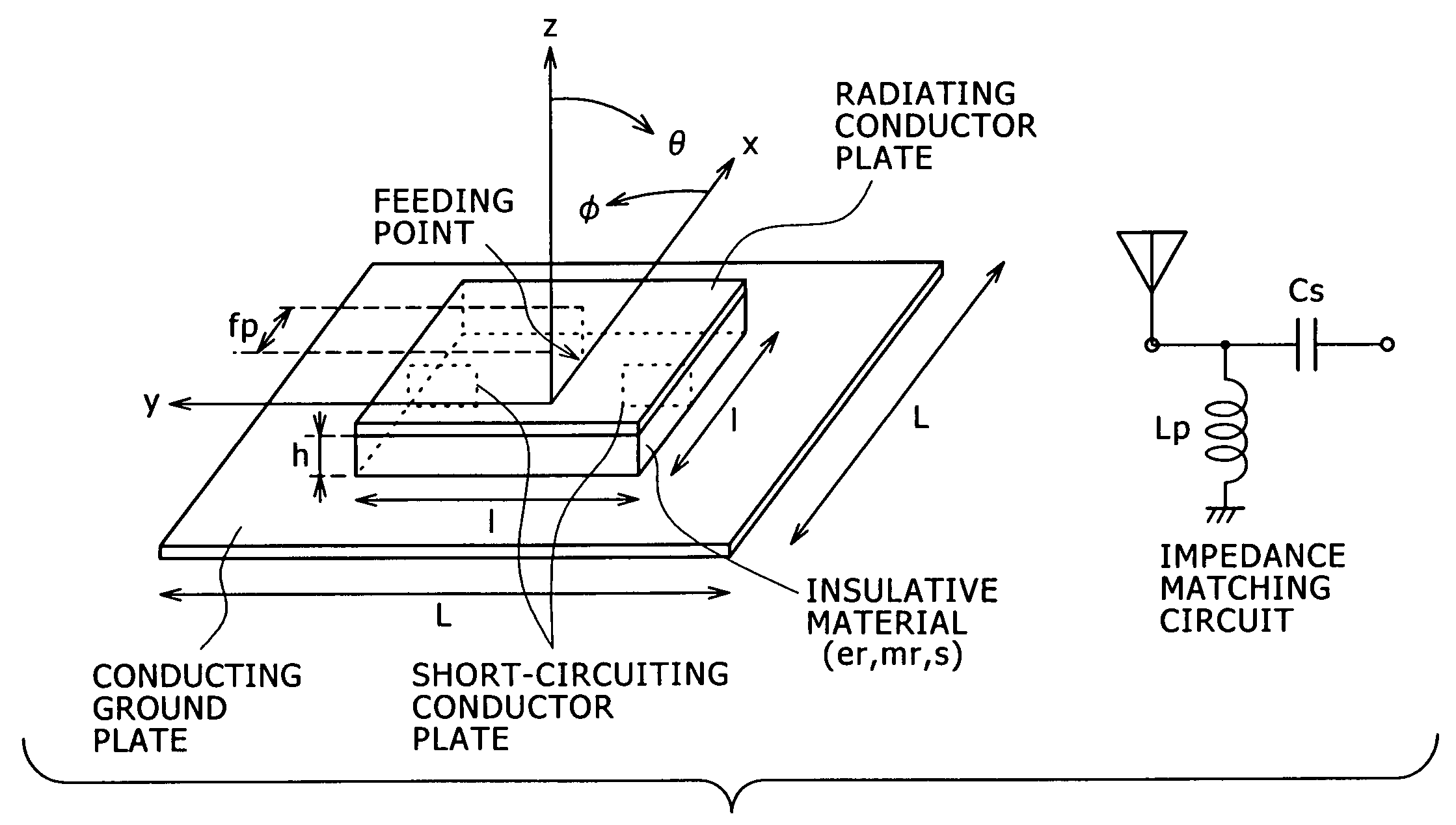
[0044]FIG. 1 schematically shows the configuration of a microstrip patch antenna according to a first embodiment of the present invention;

[0045]As shown in FIG. 1, the microstrip patch antenna is a flat antenna including a radiating conductor and a reference conductor disposed opposite to each other using an intermediate including substance having appropriate insulation. In FIG. 1, the origin of the xy coordinate system is placed at the center of the radiating conductor. The z-axis is settled along a direction orthogonal to the xy plane. For excitation, a feeding point is provided at a position with offset fp from the center of the radiating conductor, i.e., the xy origin.

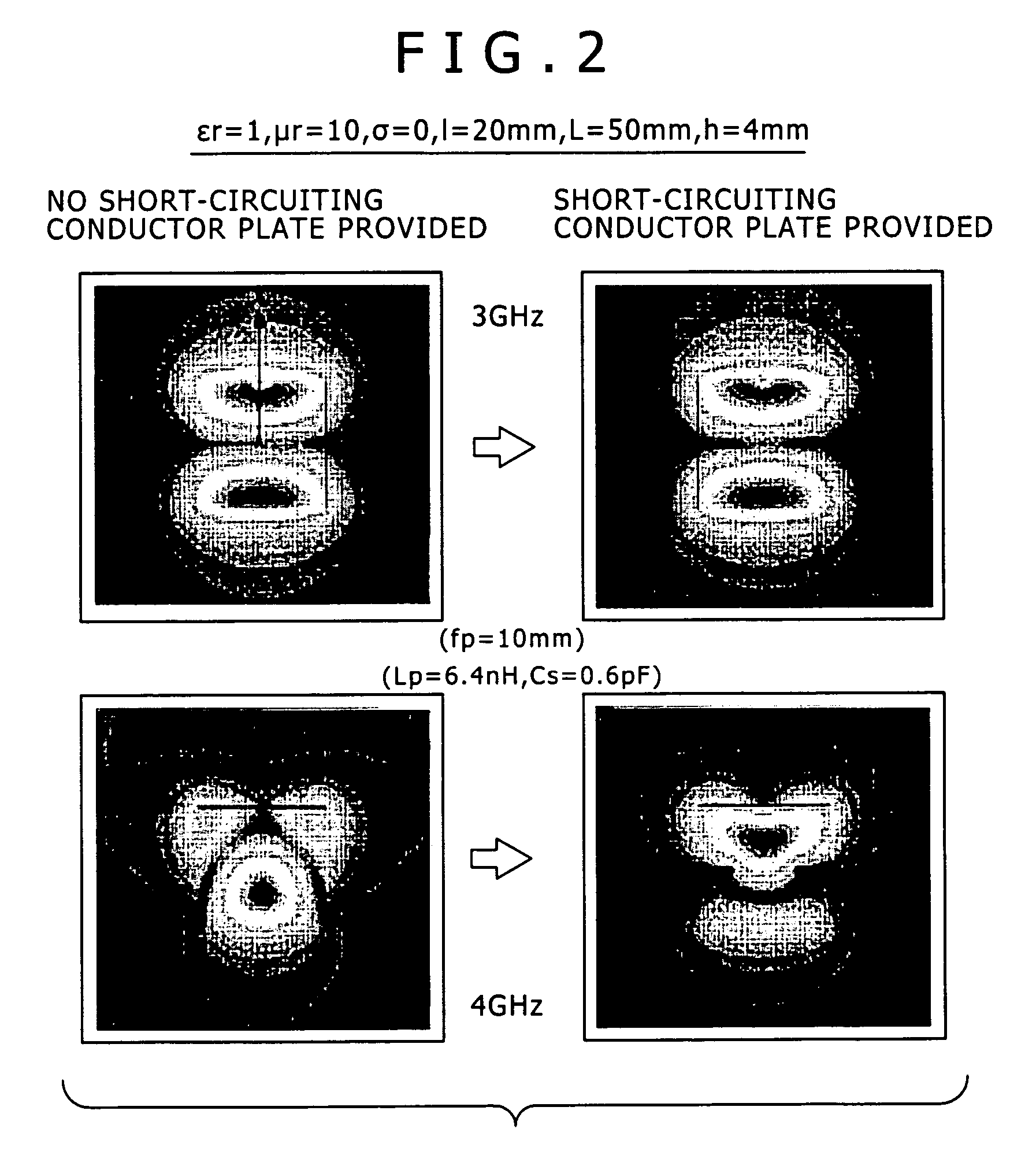
[0046]The embodiment uses a magnetic material (relative magnetic permeability>1) as an insulative material for wide band operations. The embodiment is configured to appropriately dispose a shor...


PUM


Abstract

Disclosed is a flat-type antenna apparatus which has a radiating conductor and a reference conductor disposed opposite to each other and performs feeding between the radiating conductor and the reference conductor at a position offset from the center of the radiating conductor center. The antenna includes: an insulative material layer which has relative magnetic permeability greater than 1 and is placed in a gap between the radiating conductor and the reference conductor; and a short-circuiting conductor which is disposed at a position to suppress unintended excitation and enables electric conduction between the radiating conductor and the reference conductor.

Description

CROSS REFERENCES TO RELATED APPLICATIONS[0001]The present invention contains subject matter related to Japanese Patent Application JP 2004-091968 filed in the Japanese Patent Office on Mar. 26, 2004, the entire contents of which being incorporated herein by reference.BACKGROUND OF THE INVENTION[0002]The present invention relates to an antenna apparatus used to send and receive radio signals. Specifically, the present invention relates to an ultra wide band, small-size antenna apparatus capable of being applied to a wireless communication system which uses ultra wide band frequency bands such as ultra wide band communication for transmission and reception.[0003]In more detail, the present invention relates to an antenna apparatus according to the patch antenna scheme configured by disposing a radiating conductor and a reference conductor (ground conductor) opposite to each other through an intermediate of insulative substance. Furthermore specifically, the present invention relates t...

Claims


Application Information

Patent Timeline
Patent Type & Authority Patents(United States)
IPC IPC(8): H01Q1/38H01Q1/00H01Q13/08H01Q1/24H01Q5/00H01Q9/04
CPCH01Q1/24H01Q5/50H01Q9/0421A45C11/00A45C2011/002
Inventor KURODA, SHINICHIYAMAURA, TOMOYAIGA, AKIRAOKAYAMA, KATSUMI
Owner SONY CORP
Why Eureka
Try Eureka