Multi-band compact PIFA antenna with meandered slot(s)

a pifa antenna and compact technology, applied in the field of planar antennas, can solve the problem that the diversity operation of small dual-band pifa antennas is not easy, and achieve the effect of improving the bandwidth and/or the number of operation bands

Active Publication Date: 2009-01-27
AVAGO TECH INT SALES PTE LTD
View PDF11 Cites 13 Cited by
  • Summary
  • Abstract
  • Description
  • Claims
  • Application Information

AI Technical Summary

Benefits of technology

[0017]So, the object of this invention is to improve the situation and more precisely to improve the bandwidth and / or the number of operation bands of compact PIFA antennas, while still allowing diversity reception to be achieved.

Problems solved by technology

A known problem is that small dual-band PIFA antennas are required for diversity operation.

Method used


Image

  • Multi-band compact PIFA antenna with meandered slot(s)
  • Multi-band compact PIFA antenna with meandered slot(s)
  • Multi-band compact PIFA antenna with meandered slot(s)

Examples


Embodiment Construction

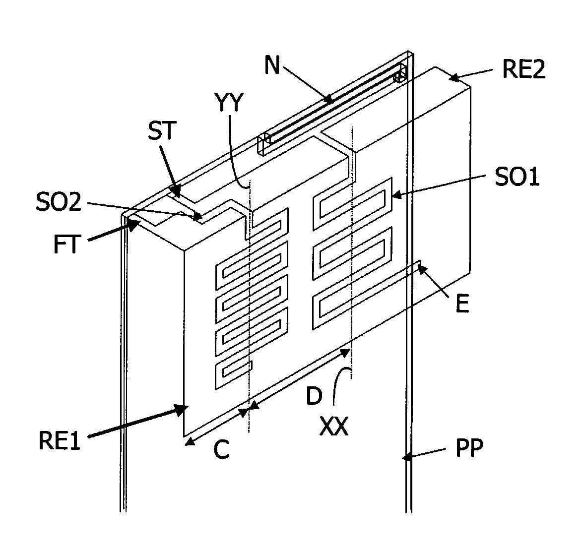
[0043]The invention proposes to mount a compact PIFA antenna assembly having at least one meandered slot in the space within a mobile phone normally previously occupied by a larger antenna. A first example of embodiment of such a PIFA antenna is illustrated in FIG. 4.

[0044]The compact antenna assembly, according to the invention, comprises a PIFA antenna mounted on a printed circuit board (PCB) PP. The PIFA antenna comprises a radiating element RE1, RE2, a feed tab (or pin) FT and a (dual-banding) main slot SO1 defined in the radiating element RE1, RE2.

[0045]The radiating element comprises first RE1 and second RE2 parts approximately perpendicular one to the other and having preferably approximately a rectangular shape. The first part RE1 is located in a first plan facing and parallel to a ground plane mounted on a face of the printed circuit board (PCB) PP. The second part (or top plate) RE2 is located in a second plane perpendicular to the ground plane.

[0046]The feed tab FT extend...


PUM


Abstract

A planar antenna assembly comprises a Planar Inverted F Antenna mounted on a printed circuit board (PP) and comprising i) a radiating element (RE1, RE2) comprising first (RE1) and second (RE2) parts approximately perpendicular one to the other and being respectively located in a first plan facing and parallel to a ground plane mounted on a face of the printed circuit board (PP) and in a second plane perpendicular to said ground plane, ii) a feed tab (FT) extending from said second part (RE2) to said printed circuit board (PP), and iii) a main slot (SO1) having a chosen length and comprising a linear part (LP) defined in the second part (RE2) at a chosen location between lateral sides of the radiating element (RE1, RE2) and a meandered part (MP) extending the linear part (LP) into the first part (RE1). The second part (RE2) is arranged such that without the main slot (SO1) high and low frequency bands are equally capacitive and inductive respectively, and the length of the main slot (SO1) is such that it is electrically quarter-wave long at approximately the geometric mean of the low and high frequency bands.

Description

FIELD OF THE INVENTION[0001]The present invention relates to improvements in or relating to planar antennas, particularly, but not exclusively, to antennas for use in portable telephones. Such telephones may operate in accordance with the GSM and DCS 1800 standards.[0002]PIFAs (Planar Inverted-F Antennas) are used widely in portable telephones because they exhibit low SAR (Specific Adsorption Ratio) which means that less transmitted energy is lost to the head and they are compact which enables them to be installed above the phone circuitry thereby using space within the phone housing more effectively. Such antennas are normally mounted on the back of the phone's plastic cover (or on an inner cover).BACKGROUND OF THE INVENTION[0003]As illustrated in FIG. 1 a typical dual-band PIFA has a radiating element RE connected to the phone printed circuit board (PCB) PP, which comprises a ground plane, through feed FT and shorting ST tabs (or pins). The radiating element RE also comprises a sl...

Claims


Application Information

Patent Timeline
Patent Type & Authority Patents(United States)
IPC IPC(8): H01Q13/10H01Q1/24H01Q1/36H01Q5/00H01Q5/10H01Q5/40H01Q9/04H01Q21/28H01Q21/29
CPCH01Q1/243H01Q1/245H01Q1/36H01Q5/40H01Q9/0442H01Q21/28H01Q21/29H01Q9/0421
Inventor BOYLE, KEVIN ROBERT
Owner AVAGO TECH INT SALES PTE LTD
Why Eureka
Try Eureka