Method of designing optical pulse shaping device and optical pulse shaping device

a technology of optical pulse shaping and shaping device, which is applied in the direction of optics, optical light guides, instruments, etc., can solve the problems of deformation of optical pulse quality and the inability to meet material processing purposes of optical pulses with no pedestals, and achieve the effect of reducing deterioration (distortion) and high quality

Active Publication Date: 2009-01-27
FURUKAWA ELECTRIC CO LTD
View PDF5 Cites 13 Cited by
  • Summary
  • Abstract
  • Description
  • Claims
  • Application Information

AI Technical Summary

Benefits of technology

[0044]With the present invention, an optical pulse output from an optical pulse shaper including an optical propagation line unit (a plurality of optical propagation line units concatenated) of concatenation of a nonlinear medium and a dispersion medium has a waveform with approximately the same peak to pedestal ratio as the waveform of an optical pulse supplied to the optical pulse shaper. Accordingly, it is possible to sufficiently suppress deterioration (distortion) occurring in the optical pulse waveform output from the optical pulse shaper thereby to output an optical pulse train of extremely high quality.
[0045]Further, if a dispersion value and a length of the first optical propagation line unit through which an input pulse first propagates and a peak power of the input optical pulse are determined, it is possible to uniquely determine dispersion values and lengths of the second and later optical propagation line units provided as subsequent steps. Therefore, designing of the optical fiber shaper is significantly facilitated.
[0046]Furthermore, if the dispersion value of a nonlinear medium of the first optical propagation line unit is zero or near zero, dispersion values of respective nonlinear media of the second and later optical propagation line units provided as subsequent steps become approximately the same as the dispersion value of the nonlinear medium of the first optical propagation line unit, and therefore, designing of the optical fiber shaper is further facilitated.

Problems solved by technology

In the SC compression, a large compression ratio can be obtained, however there are problems of degradation of pulse quality and the like because of a pedestal component included in the width of a compressed optical pulse.
Therefore, the optical pulse with no pedestal is suitable for material processing purposes.

Method used


Image

  • Method of designing optical pulse shaping device and optical pulse shaping device
  • Method of designing optical pulse shaping device and optical pulse shaping device
  • Method of designing optical pulse shaping device and optical pulse shaping device

Examples


Embodiment Construction

[0081]Description below will be made about an embodiment to which the present invention is applied.

[0082]First description is about a configuration of an optical pulse outputting device 100 having an optical pulse shaper 30 to which the present invention is applied, and then, about the design theory of the optical pulse shaper 30. Last description is about specific examples of a detailed design of the optical pulse shaper 30 based o this design theory.

100.

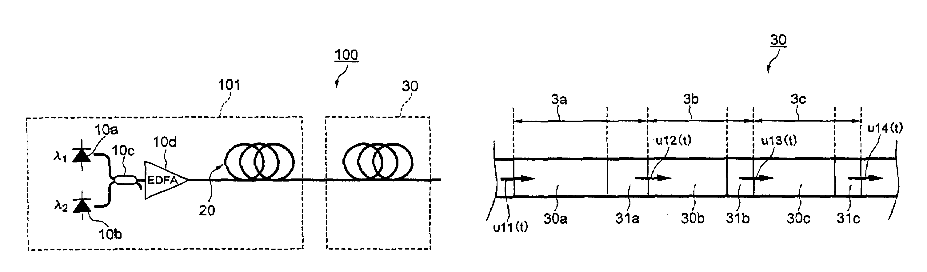
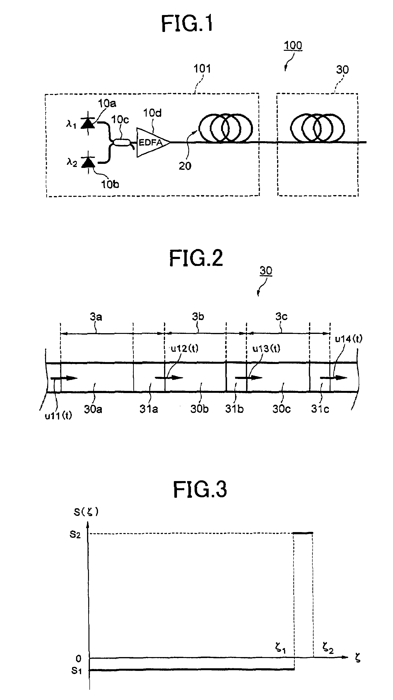
[0083]First, FIG. 1 is referred to explain the configuration of an optical pulse outputting device 100 based on the design theory, which will be described in detail later.

[0084]As shown in FIG. 1, the optical pulse outputting device 100 has an optical pulse supplying device 101 and the optical pulse shaper 30 for compressing the pulse width of optical pulses output from the optical pulse supplying device 101.

[0085]The optical pulse supplying device 101 has a dual-frequency optical source 10 and an optical pulse shaper 20.

[0086]The ...


PUM

PropertyMeasurementUnit
repetition frequencyaaaaaaaaaa
peak poweraaaaaaaaaa
total length zAnaaaaaaaaaa

Abstract

The present invention provides a method for designing an optical pulse shaper including a first optical propagation line unit having a nonlinear medium and a dispersion medium concatenated, including: specifying design specifications of the first optical propagation line unit; and based on the design specification, calculating a quasi-periodic stationary pulse of which a waveform of an input optical pulse to the first optical propagation line unit is similar to a waveform of an output pulse from the first optical propagation line unit.

Description

TECHNICAL FIELD[0001]The present invention relates to an optical pulse shaper and a method for designing the optical pulse shaper that are applicable to optical pulse generating techniques used in an optical fiber communication system, or applicable to optical pulse generating techniques used for materials processing purposes.BACKGROUND INVENTION[0002]Recently, there has been a rapidly increasing importance of an optical pulse shaper for generating and outputting ultra-short optical pulses.[0003]In the area of optical communications, with use of a system in which a bit rate of each channel exceeds 40 Gb / s, a repetition frequency is substantially high, and accordingly, optical pulses are required to have high quality, less noise, less jitter and the like. In addition, when a relay unit is inserted into an optical propagation line, it is required to generate local clock pulse trains for a function of optical signal regeneration to recover from waveform-deteriorated optical pulses caus...

Claims


Application Information

Patent Timeline
Patent Type & Authority Patents(United States)
IPC IPC(8): G02B6/00G02F1/365
CPCG02F1/365G02F2203/26G02F2203/54
Inventor INOUE, TAKASHINAMIKI, SHU
Owner FURUKAWA ELECTRIC CO LTD
Why Eureka
Try Eureka