Aircraft engine arrangement

a technology for aircraft engines and nacelles, which is applied in the direction of machines/engines, jet propulsion plants, gas turbine plants, etc., can solve the problems of affecting the drag coefficient of aircraft, affecting the aerodynamic shape of aircraft or nacelles, and affecting the aerodynamic effect of aircraft, so as to achieve the effect of reducing aerodynamic drag

Inactive Publication Date: 2009-02-03
ROLLS ROYCE PLC
View PDF18 Cites 40 Cited by
  • Summary
  • Abstract
  • Description
  • Claims
  • Application Information

AI Technical Summary

Benefits of technology

[0013]Preferably, the engine is surrounded by a nacelle to minimise aerodynamic drag.

Problems solved by technology

However, one disadvantage is that aerodynamic shape of the airframe or nacelle is compromised with bulging to accommodate the accessories.
Clearly, any bulging can be streamlined but by implication will be detrimental to the aircraft drag coefficient due to steeper cowl angles required to clear the engine accessories.
Although this engine configuration is shorter by virtue of the reverse flow combustor, it is seriously disadvantaged as reversing the gas flow induces substantial flow energy losses and causes gas flow disruption into the combustor.
Thus the bypass gas flow is subject to substantial energy losses ingressing, flowing through and egressing the discrete bypass tubes.
Furthermore, GB744,695 does not disclose either a fairing spanning across a bypass duct or of mounting accessories within such a fairing.
The engine of GB744,695 is not suitable for high-speed or super-sonic flight.

Method used


Image

  • Aircraft engine arrangement
  • Aircraft engine arrangement
  • Aircraft engine arrangement

Examples


Embodiment Construction

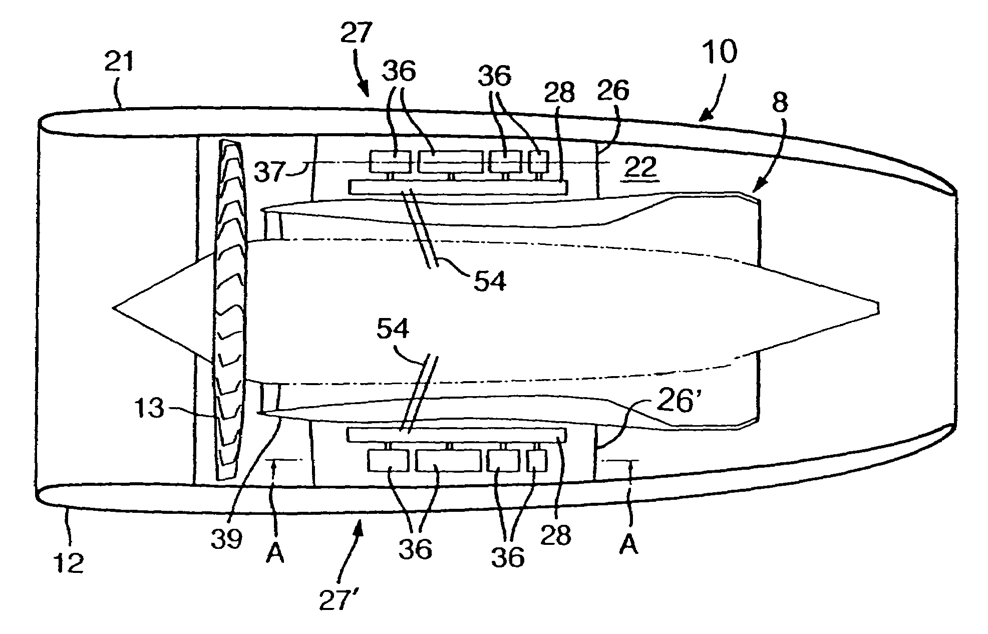
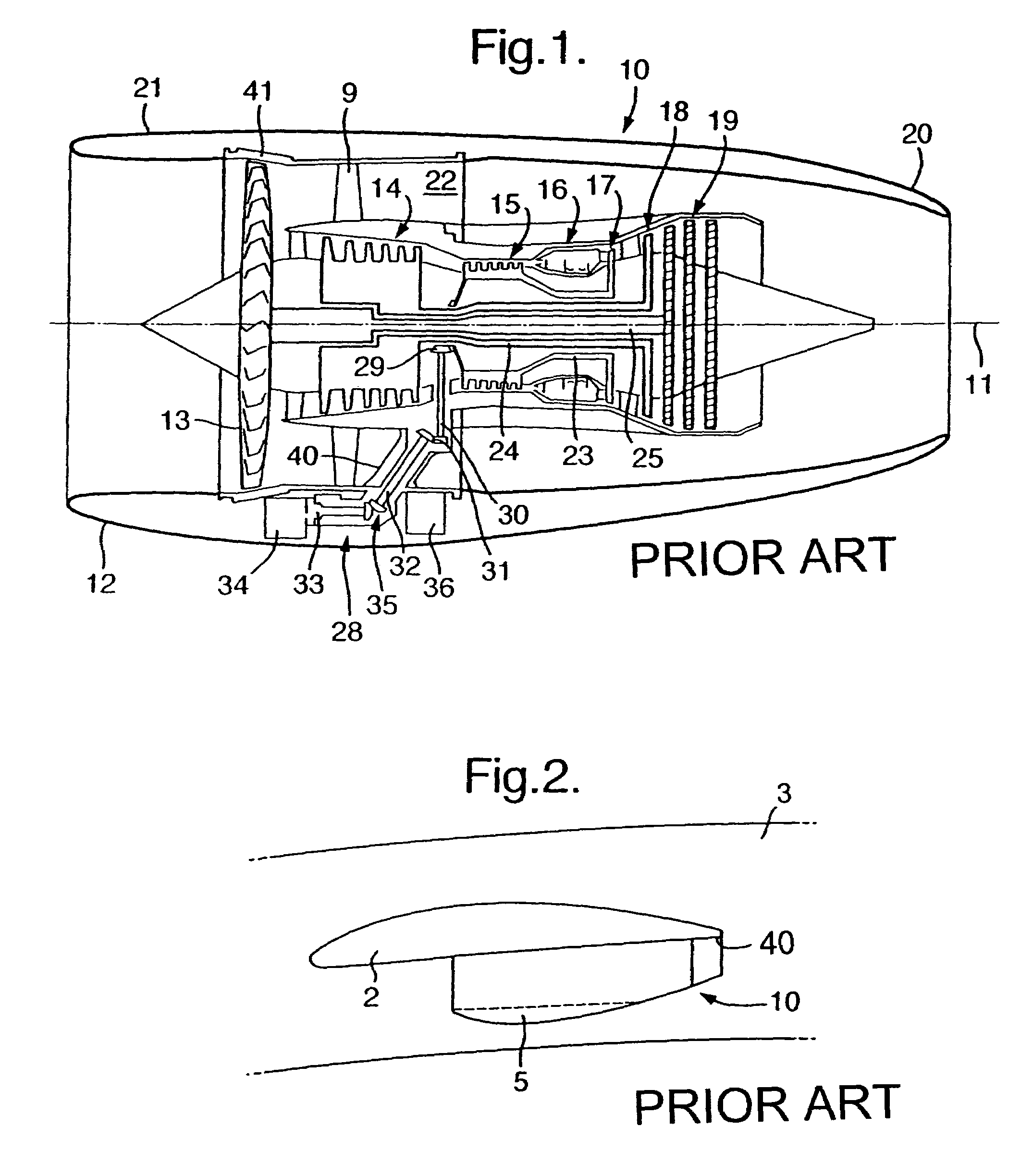
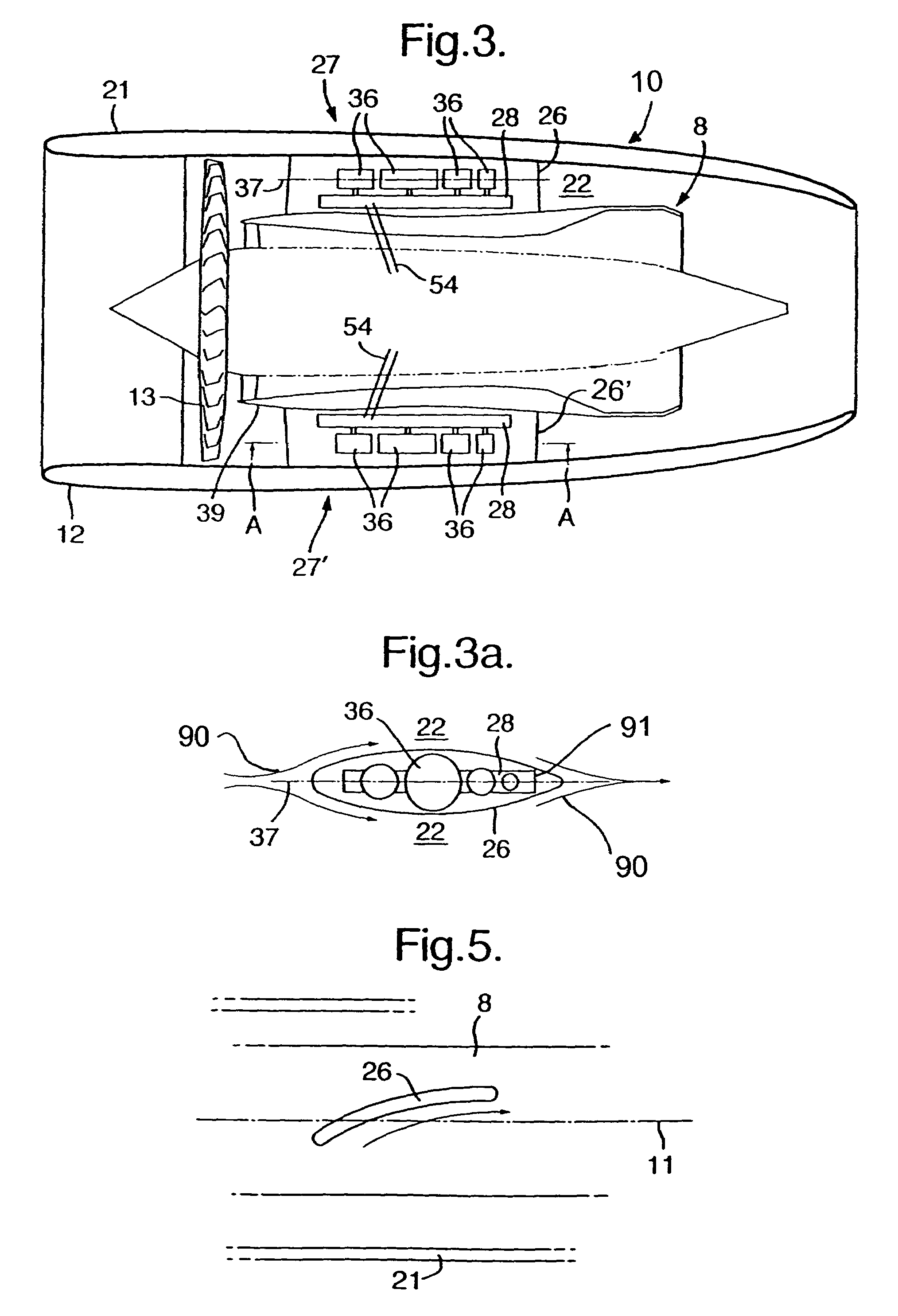
[0028]With reference to FIG. 1, a conventional prior art ducted fan gas turbine engine generally indicated at 10 has a principal and rotational axis 11. The engine 10 comprises, in axial flow series, an air intake 12, a propulsive fan 13, and a core engine 8 itself comprising an intermediate pressure compressor 14, a high-pressure compressor 15, combustion equipment 16, a high-pressure turbine 17, and intermediate pressure turbine 18, a low-pressure turbine 19; the engine 10 further comprises an exhaust nozzle 20. A nacelle 21 generally surrounds the engine 10 and defines both the intake 12 and the exhaust nozzle 20.

[0029]The gas turbine engine 10 works in a conventional manner so that air entering the intake 12 is accelerated by the fan 13 to produce two air flows: a first air flow into the core engine 8 and on through the intermediate pressure compressor 14 and a second air flow which passes through a bypass duct 22 to provide propulsive thrust. The intermediate pressure compresso...


PUM


Abstract

In order to avoid external bulging (5) to accommodate accessory mechanisms (27) and gearboxes (30) to drive these mechanisms (27) in accordance with the present invention splitter fairings (26) are located within a bypass duct (23) of an engine (20). The bypass duct (23) is defined between a casing (21) and compressor/turbine propulsion core (22). The fairings (26) are of sufficient dimensions to accommodate the accessory mechanisms (27) whilst the bypass duct (23) is appropriately shaped axi-symmetrically to eliminate and balance any blocking effect of these fairings (26) within the duct (23) upon air flow (24). Further fairings (26′) may be provided to accommodate oil tank reservoirs (34) as well as filter/heat exchanger mechanisms (35) for the engine (20). In such circumstances, a notional elongate cylindrical profile for the engine (20) is maintained such that a reduced cross section is require for that engine (20) and so allowing a smaller airframe with better sonic boom signature.

Description

[0001]This application is a continuation of PCT / GB04 / 02801, filed Jun. 30, 2004.FIELD OF THE INVENTION[0002]The present invention relates to aircraft engine arrangements and more particularly to engine arrangements used in relatively high speed or super-sonic aircraft applications.BACKGROUND OF THE INVENTION[0003]In a relatively modern aero-gas turbine engine certain accessories, such as the gearbox and electrical starter / generator, are mounted outwardly of the fan casing within the nacelle or airframe within which the engine is embedded. Accessory services, such as oil feed pipes and electrical cables, are routed through fairings spanning across the bypass duct. These fairings do not carry structural loads, but provide an aerodynamic shape around the accessory services.[0004]To minimise aerodynamic drag the nacelle or airframe is tightly wrapped around the engine, minimising frontal area. However, one disadvantage is that aerodynamic shape of the airframe or nacelle is compromised ...

Claims


Application Information

Patent Timeline
Patent Type & Authority Patents(United States)
IPC IPC(8): F02C7/32F02K3/04
CPCF02C7/32F02K3/04
Inventor STRETTON, RICHARD G
Owner ROLLS ROYCE PLC
Why Eureka
Try Eureka