Air-guiding assembly for reducing wind drag

a technology of air-guiding assembly and wind-driven vehicle, which is applied in the direction of roofs, heating types, lighting and heating apparatus, etc., can solve the problems of direct impact on driving efficiency, affecting the driving efficiency of a common vehicle, and the kind of car or vehicle will consume fuel inevitably, so as to reduce the wind drag and reduce the wind drag. , the driving efficiency and the stability of driving of a large-sized vehicle can be improved, and the effect of reducing the wind drag

Inactive Publication Date: 2009-02-03
CHEN SHIH H
View PDF2 Cites 52 Cited by
  • Summary
  • Abstract
  • Description
  • Claims
  • Application Information

AI Technical Summary

Benefits of technology

[0007]In view of the above drawbacks, the present invention is to provide an air-guiding assembly for reducing the wind drag, in which a frame is provided at a tail end of a vehicle body to guide the airflow generated in driving, thereby changing the direction of the airflow and reducing substantially the wind drag generated in driving. Via this arrangement, the driving efficiency and the stability of driving of a large-sized vehicle can be improved.
[0008]The present invention is to provide an air-guiding assembly for reducing the wind drag, which is provided at a tail end of a vehicle body and has a hollow frame. The frame is constituted of a plurality of air-guiding plates. These air-guiding plates are each formed into a curved shape. An airflow path is formed between the air-guiding plates. The front end surface of the frame is formed with an intake port, and the rear end surface thereof is formed with an exhaust port. The intake port and the exhaust port are in fluid communication with the airflow path. The area of the intake port is larger than that of the exhaust port, so that the exhaust port acts as a nozzle. When the airflow generated in driving is compulsively guided into the intake port of the frame to pass through the airflow path and then is guided out via the exhaust port, an invisible wind wall is formed in the rear of the vehicle, thereby reducing a whirlwind region in the rear of the vehicle. Therefore, the airflow is smoother and thus the driving efficiency is improved.

Problems solved by technology

The driving efficiency of a common vehicle will be affected due to the wind drag generated by the airflow.
Although the weight of the large-sized vehicle is much larger than that of the small car, any kind of cars or vehicles will consume the fuel inevitably due to the wind drag when driving at a high speed.
However, in addition to the wind drag generated in the front end of the vehicle, the airflow passing through the vehicle body also generates a field of turbulent flow at the rear end of the vehicle body, which also affecting the driving efficiency directly.
However, in the above-mentioned prior art, since the volume of the inclined plates 20 should be large enough to support the strength of the airflow generated in driving at a high speed, which increasing the structure cost greatly.
Further, the inclined plates 20 are located at the positions that may affect the opening and closing of the doors in the rear of the vehicle body 10, which is very inconvenient in use.
Therefore, it is an import issue for those skilled in this art to solve the drawbacks of the above-mentioned prior art.

Method used


Image

  • Air-guiding assembly for reducing wind drag
  • Air-guiding assembly for reducing wind drag
  • Air-guiding assembly for reducing wind drag

Examples


Embodiment Construction

[0021]The detailed description and the technical contents of the present invention will be explained with reference to the accompanying drawings.

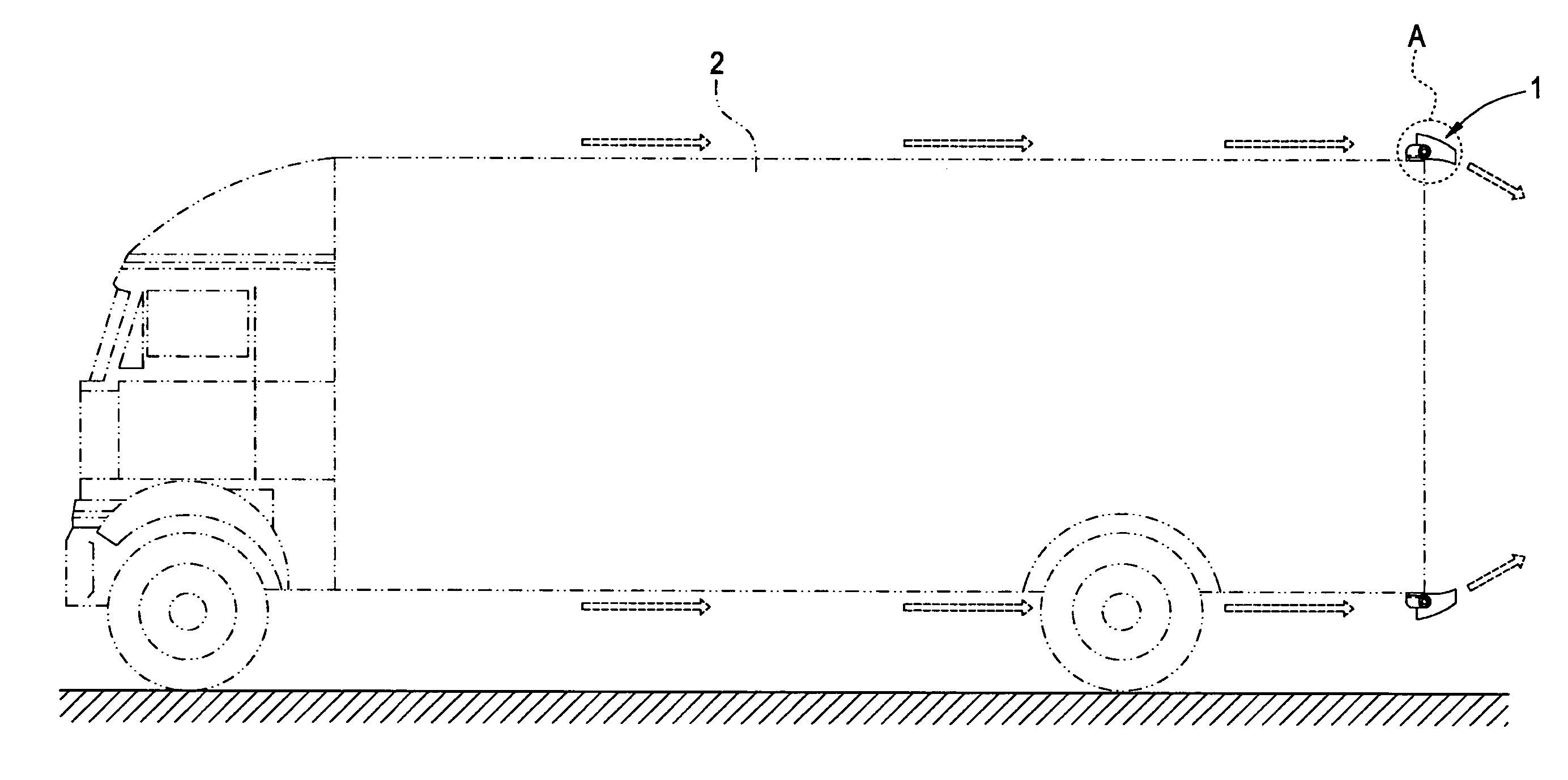
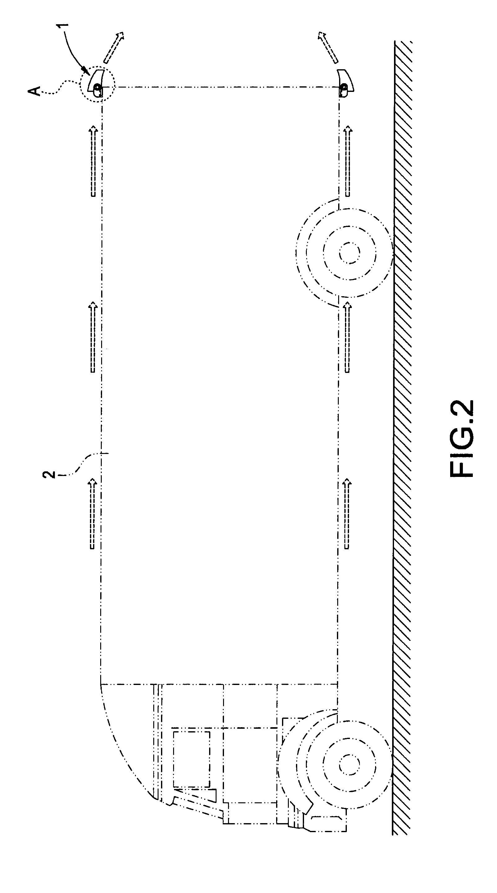
[0022]With reference to FIGS. 2 to 5, the air-guiding assembly of the present invention is mounted on the top end of a tail portion of a large-sized vehicle (shown as a big truck in the drawings), as shown in the partially enlarged view of FIG. 2. With reference to FIG. 3, the air-guiding assembly is primarily constituted of a rectangular frame 1. The frame 1 is hollow and the upper and lower ends thereof are provided with an air-guiding plate 11 and 12 respectively. An airflow path 13 is formed between the air-guiding plates 11 and 12. The surfaces of the air-guiding plates 11 and 12 are each formed into a curved shape. The front end surface of the frame 1 has an intake port, and the rear end face thereof has an exhaust port 15. The area of the intake port 14 is larger than that of the exhaust port 15, so that the exhaust port 15 substanti...


PUM


Abstract

An air-guiding assembly for reducing the wind drag is provided at a tail end of a vehicle body and has a hollow frame. The frame is constituted of a plurality of air-guiding plates. These air-guiding plates are each formed into a curved shape. An airflow path is formed between the air-guiding plates. The front end surface of the frame is formed with an intake port, and the rear end surface thereof is formed with an exhaust port. The intake port and the exhaust port are in fluid communication with the airflow path. The area of the intake port is larger than that of the exhaust port, so that the exhaust port acts as a nozzle. When the airflow generated in driving is compulsively guided into the intake port of the frame to pass through the airflow path and then is guided out via the exhaust port, an invisible wind wall is formed in the rear of the vehicle, thereby reducing a whirlwind region in the rear of the vehicle. Therefore, the airflow is smoother and thus the driving efficiency is improved.

Description

BACKGROUND OF THE INVENTION[0001]1. Field of the Invention[0002]The present invention relates to an air-guiding assembly, and in particular to an air-guiding assembly for reducing the wind drag.[0003]2. Description of Prior Art[0004]The driving efficiency of a common vehicle will be affected due to the wind drag generated by the airflow. The most common solution is to mount an air-guiding plate. In addition to small cars, large-sized vehicles that travel for a long distance especially need the air-guiding plate. Although the weight of the large-sized vehicle is much larger than that of the small car, any kind of cars or vehicles will consume the fuel inevitably due to the wind drag when driving at a high speed. The only difference lies in that the air-guiding plate is mounted on the top of the head of the large-sized vehicle in prior art and the air-guiding plate is arranged obliquely on the top of the vehicle head. With the oblique air-guiding plate, the flowing angle of the incomi...

Claims


Application Information

Patent Timeline
Patent Type & Authority Patents(United States)
IPC IPC(8): B60J1/20B60J9/04
CPCB62D35/001
Inventor CHEN, SHIH H
Owner CHEN SHIH H
Why Eureka
Try Eureka