Method for controlling air distribution in a cyclone furnace

a cyclone furnace and air distribution technology, applied in the direction of temperatue control, flame sensor, solid heating fuel, etc., can solve the problems of high nosub>x/sub>emission, inefficient boiler control, corrosion and wastage of the refractory walls of the cyclone barrel, etc., to improve the resolution of analysis techniques

Active Publication Date: 2009-02-03
ELECTRIC POWER RES INST INC
View PDF11 Cites 6 Cited by
  • Summary
  • Abstract
  • Description
  • Claims
  • Application Information

AI Technical Summary

Benefits of technology

[0020]It is another object to provide a method of enhancing proper air flow distribution in a cyclone furnace to optimize the performance of the furnace.
[0023]According to a preferred embodiment of the invention a method of adjusting air flow distribution in a cyclone furnace is disclosed. The furnace is of the type having a plurality of cyclones, each cyclone having a barrel, an attached burner on one end of the barrel and a re-entrant throat on an opposing end, primary, secondary and tertiary air flow dampers for controlling air flow to the barrel and burner, over-fire air flow dampers, a lighter scanner and a main flame scanner in order to minimize NOx while maintaining acceptable carbon monoxide emissions, unburned carbon loss, and reliable cyclone operation. The method includes the steps of setting secondary air flow on each cyclone to a typical secondary air flow damper setting to provide equal secondary air flow to each cyclone, setting all over-fire air flow dampers to a same air flow value and closing the tertiary air flow damper. The primary air flow dampers are adjusted to 90-95% of a target sum of primary air flow and tertiary air flow as indicated by one or more flow measurement devices or the position of the primary air flow damper, and the tertiary air flow damper is adjusted to provide a balance of primary and tertiary air flow as indicated by flow measurement devices or the position of the primary and tertiary air flow dampers. Cyclone performance is assessed by analyzing flame scanner signals from the main flame scanner and lighter scanner in analysis software and generating statistics indicative of whether operational characteristics of one or more cyclones is inside or outside of predetermined variance limits, and increasing primary air flow or secondary air flow as appropriate to eliminate instability indicated by some or all of statistics being outside of ± variance limits. In the case of all cyclones indicating stable operation by reference to both main flame and scanner lighter signals, the primary air flow on each cyclone is decreased until the main flame scanner signal begins to exhibit instability as indicated by statistics drifting toward variance limits, while maintaining tertiary air flow at minimum flow. Upon adjustment of the primary air flow to a minimum value needed to achieve stable operation, secondary air flow is decreased by closing the secondary air damper on each cyclone stepwise and simultaneously until the lighter scanners begin to detect instability. Air flow to all overfire air ports is increased equally to maintain excess air flow while decreasing secondary air flow to the cyclones to a value corresponding to a minimum secondary air flow and maximum degree of staging for each cyclone and the overfire air ports dampers are adjusted as needed to compensate for any O2 or CO imbalances resulting from the adjustments made to the cyclones.
[0034]In accordance with another embodiment of the invention, the method includes the step of constraining any overcompensation in an air flow control algorithm by using a moving average of the statistics smooth out spikes in the statistics and provide a more representative process variable to guide the control system response.

Problems solved by technology

Inefficient boiler control is responsible for wasting large amounts of fuel and releasing nitrogen oxide pollutants into the atmosphere.
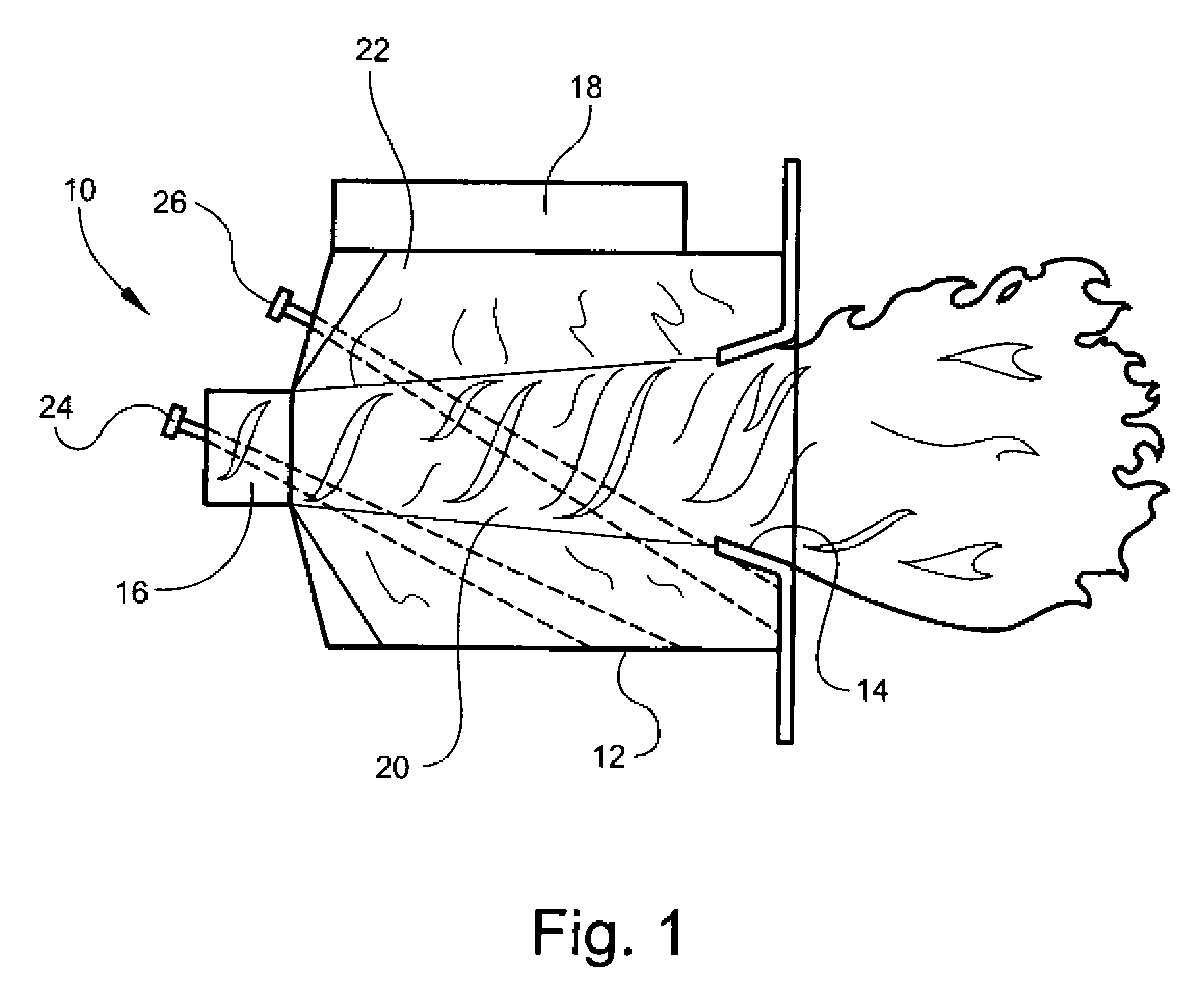
Historically, the cyclonic flow in the cyclone furnace has led to very high combustion temperatures, which, although providing very efficient combustion, has also led to high NOx emissions.
First, in the absence of sufficient oxygen, the fuel nitrogen will recombine with itself to form molecular nitrogen rather than NO.
Although NOx emissions have been reduced considerably with this technique it has led to two significant operational problems.
First, under reducing conditions (i.e., stoichiometries less than 1.0 molar ratio of air / fuel) corrosion and wastage of the refractory walls of the cyclone barrel is accelerated.
Second, lower temperatures in the cyclone barrel may cause the temperature of the molten slag to fall below its melting temperature and freeze.
This leads to high unburned carbon losses from the boiler and lower boiler efficiency.
Further, other characteristics of the coal, such as moisture and grind size can negatively impact combustion in the cyclone.
Since the lighter typically uses a premium fuel such as natural gas or oil, this is an expensive corrective action.
This action increases combustion in the vicinity of the frozen slag and consequently raises the temperature of the slag.
The procedure for tuning the cyclones to optimize performance is iterative and time-consuming.
Temporary, expensive gas sample grids must be installed in the flue at the exhaust of the boiler to measure the concentration of carbon monoxide and unburned carbon in the combustion gases.
First, prior to the discovery contained in this application it was not known whether or not it would be possible to correlate the flame characteristics with excess air, air distribution, NOx emissions, slag tap operation or some other aspects of cyclone operation.
Second, it was not known if a method could be developed to adjust the air flow distribution within the cyclone using the analysis results to optimize the cyclone performance.
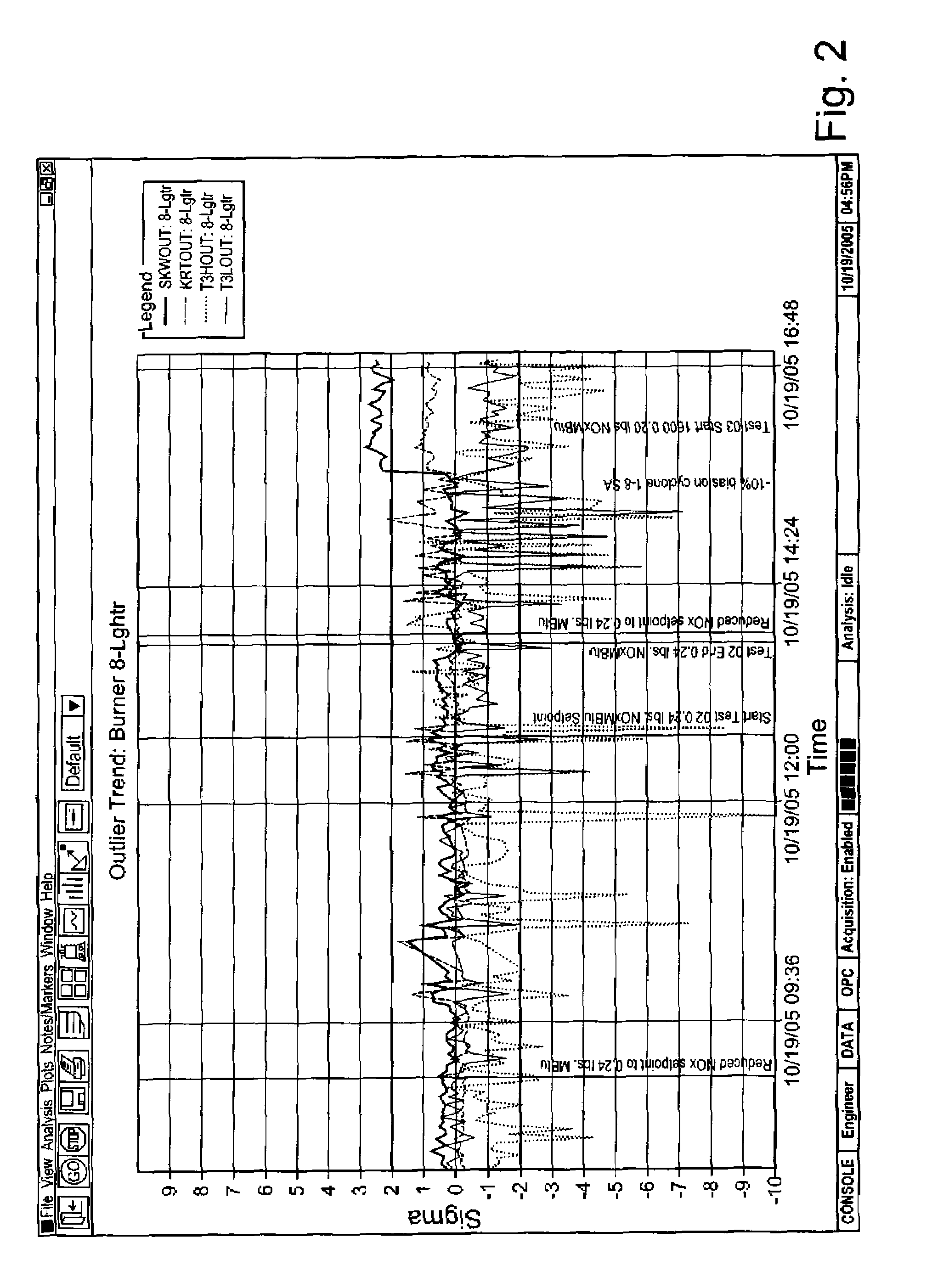
However, large fluctuations in NOx emissions and carbon burnout can occur in individual burners over short time scales (i.e., between about 10 seconds to fractions of a second).
Cyclone furnaces contain added complexity that demands a more sophisticated combustion monitoring approach.
If the slag freezes, the combustion in the cyclone will deteriorate and an unacceptable amount of the fuel may leave the cyclone unburned.
However, carbon monoxide and unburned carbon emissions may increase if the A / F ratio is too low.
The A / F ratio also affects slagging, fouling and corrosion phenomena that typically occur in the combustion zone.
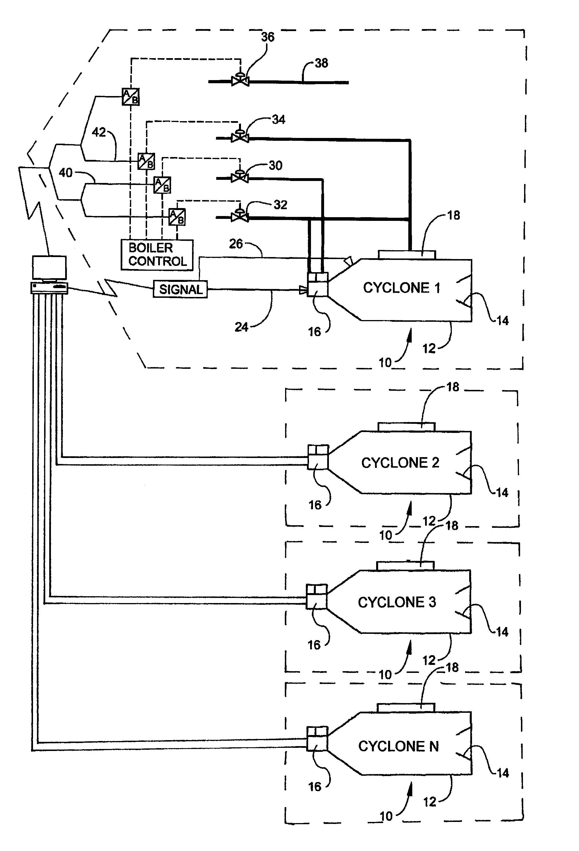
Unfortunately, in multi-burner or multi-cyclone steam generator furnaces the A / F ratio may differ from burner to burner, or cyclone to cyclone.
Since both combustion efficiency and NOx generation levels depend on the localized values of the A / F ratio (i.e., the distribution and mixing within each flame), measurement and control of the global A / F ratio alone does not necessarily optimize performance.
The complexity of the process is further increased by the presence of both solids and volatile components in the fuel, which mix and burn at characteristically different rates.
Extinction of combustion in the burner can occur if the primary air flow is too high, if there is an excessive amount of moisture present in the fuel or if the fuel is too coarse or a combination of all three.
These changes in properties cause a delay in the release of volatile matter from the fuel resulting in a gas mixture outside of the flammability limit.
Whether caused by high air velocity or excessively fuel-rich burner conditions, delayed combustion in the burner is an undesirable operating condition typically associated with excessive emissions of pollutants.
Currently, there is no good way to identify that the optimum amount of primary air is being fed to the burner.
Knowing the air flow alone is not sufficient.
Conventional signal analysis methods such as Fourier analysis and univariate statistics are based on assumptions that are not entirely valid for combustion in a cyclone burner or barrel.
Chaos theory (especially, symbol sequence techniques and temporal irreversibility) avoids the assumptions of conventional analytical methods and thus may provide information unavailable from these well-known techniques.

Method used


Image

  • Method for controlling air distribution in a cyclone furnace
  • Method for controlling air distribution in a cyclone furnace
  • Method for controlling air distribution in a cyclone furnace

Examples


Embodiment Construction

[0043]Referring now specifically to the drawings, a typical cyclone of the type utilized in the practice of the methods according to this invention is shown generally in FIG. 1 at reference numeral 10.

[0044]The cyclone 10 includes a barrel 12 having a re-entrant throat 14. A burner 16 is mounted so as to project a flame into the re-entrant throat 14. The burner 16 may be of the radial, scroll or vortex type. A secondary air throat 18 mounted in an offset position between the burner 16 and the re-entrant throat 14. The interior of the barrel 12 defines a central vortex zone 20 and a surrounding recirculation zone 22. A main flame scanner 24 and a lighter scanner 26 are positioned to detect conditions and generate signals within the barrel 12 and burner 16 indicative of the operation of the system.

[0045]The main flame scanner 24 detects flame instabilities resulting from insufficient primary and / or tertiary air in the burner 16. The lighter scanner 26 detects flame instabilities resul...


PUM


Abstract

Methods for cyclone boiler flame diagnostics and control, including methods for monitoring the operating state of a cyclone furnace using linear and nonlinear signal analysis techniques, including temporal irreversibility and symbol sequence. Adjustments may be made in the air flow distribution to optimize performance. Signals for the main flame and lighter scanners are relatively independent, thereby allowing for independent control of the primary air flow to the burner and secondary air flow to the barrel.

Description

TECHNICAL FIELD AND BACKGROUND OF INVENTION[0001]The present invention relates to methods for cyclone boiler flame diagnostics and control. More particularly, the present invention provides methods for monitoring the operating state of a cyclone furnace using linear and nonlinear signal analysis techniques, including temporal irreversibility and symbol sequence. Adjustments may be made in the air flow distribution to optimize performance. Economic pressures and increasingly restrictive environmental regulations have contributed to an increasing need for advanced control systems that efficiently regulate utility boilers. Inefficient boiler control is responsible for wasting large amounts of fuel and releasing nitrogen oxide pollutants into the atmosphere.[0002]In particular, industrial and utility cyclone boiler operators need a better indication of the overall combustion condition in the cyclone furnace. A cyclone furnace consists of two combustion cavities—the burner and the barrel...

Claims


Application Information

Patent Timeline
Patent Type & Authority Patents(United States)
IPC IPC(8): F23M3/00
CPCF23C7/008F23C7/02F23N3/002F23N3/08F23N5/082F23N2023/46F23N2029/16F23N2223/46F23N2229/16Y10T137/0419
Inventor FLYNN, THOMAS J.BAILEY, RALPH T.FULLER, TIMOTHY A.FINNEY, CHARLES E. A.DAW, C. STUART
Owner ELECTRIC POWER RES INST INC
Why Eureka
Try Eureka