Prosthesis

a technology of protruding acetabular parts and flanges, applied in the field of prosthesis, can solve the problems of reducing the risk of cross-section as the screw is inserted into the aperture in the flange, affecting the function of the flange, and reducing the risk of cross-section as the screw is inserted into the apertur

Active Publication Date: 2009-02-03
FINSBURY DEV
View PDF18 Cites 46 Cited by
  • Summary
  • Abstract
  • Description
  • Claims
  • Application Information

AI Technical Summary

Benefits of technology

[0024]In a preferred arrangement of the present invention two pairs of flanges will be present. This enables two fixation means to be used thereby improving the strength of the attachment to the pelvis. It will be understood that corresponding flanges in each pair will preferably be positioned such that they are parallel.
[0026]As explained above, the pair of flanges are angled downwardly from the rim of the cup. This angle θ, which is defined with reference to the plane extending across the rim of the cup, may be selected to be any suitable angle which enables the fastening means to be inserted into the pelvis. Angles in the region of from about 0° to about 30° are suitable with angles of from 10° to about 25° being more preferred. In some arrangements, angles in the region of 20° offer various advantages. This arrangement will direct the screws into the available bone in such a manner that the longest possible fastening means may be used which will provide optimum support for the implant.
[0027]Each of the pair of flanges is angled at an angle α to a plane extending across the apex of each of the flanges. α may be of any suitable value which will enable the fastening means to be passed into the pelvis at an appropriate angle to hold the acetabular component in place. Angles in the region of about 10° to about 40° may be suitable. However, in order that the fastening means can be passed into the bone at the optimum angle such that they are loaded in compression, α is preferably in the region of about 20°. Having the fastening means loaded in compression reduces the risk of the fastening means failing with prolonged use.
[0030]The screws may be chosen to have deeper flutes at the tip end than have been used heretofore. In one arrangement, the thread may be tapered. One benefit of tapering the thread toward the tip is that the risk of cross-section as the screw is inserted into an aperture in the flange is reduced.

Problems solved by technology

Diseases such as rheumatoid- and osteo-arthritis can cause erosion of the cartilage lining of the acetabulum so that the ball of the femur and the hip bone rub together causing pain and further erosion.
Bone erosion may cause the bones themselves to attempt to compensate for the erosion which may result in the bone being reshaped.
This misshapen joint may cause pain and may eventually cease to function altogether.
A major factor influencing the life expectancy of a prosthetic implant is wear of the articulating surface.
These particles can cause osteolysis and adverse tissue reactions which will lead to loosening of the component and reduce implant life.
However in a young patient, it is likely that one or more revision operations will have to be performed during the lifetime of the patient.
One problem associated with these revision operations is that it is more difficult to get a tight fit between the replacement acetabular component and the pelvis due to further degradation of the bone.
As this prosthesis has several separate elements, it can be difficult to fit.
One problem associated with arrangements in which the cup is held in place by screws located through the cup is that interaction between the head of the femur may cause wear.
It will be understood that the presence of screw holes in the cup disrupts the articulating surface which is disadvantageous particularly where the interface between the articulating components is metal / metal.
However, since the angling of the lug means that the acetabular component is orientation specific, separate components must be manufactured for the left and right side which increases the manufacturing costs.
The modular systems can be expensive to manufacture and difficult to fit.
Many of the systems only allow for short screws to be used due to the angle in which they are inserted into the bone and thus the support for the acetabular component may not be sufficient for prolonged use.
Finally, the components may be orientation specific to only the left or right acetabulum thereby increasing the costs of manufacture.
In some arrangements, the insertion of the screws may cause the acetabular component to be pulled out of alignment.

Method used


Image

  • Prosthesis
  • Prosthesis
  • Prosthesis

Examples


Embodiment Construction

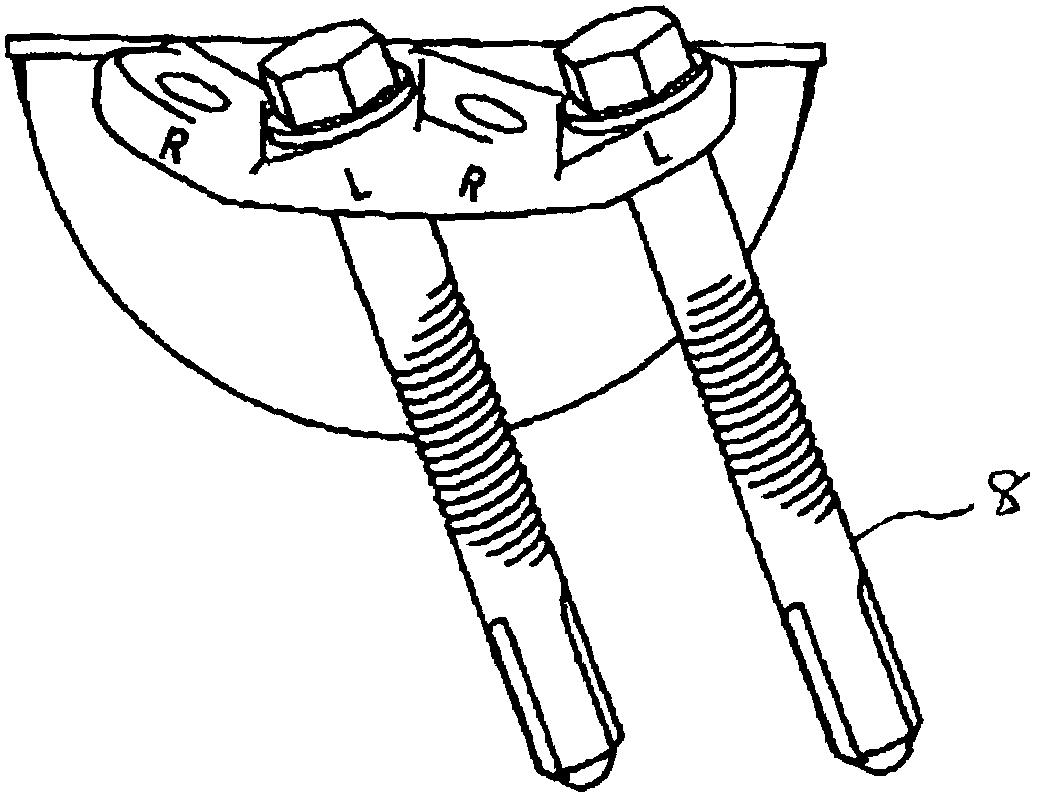
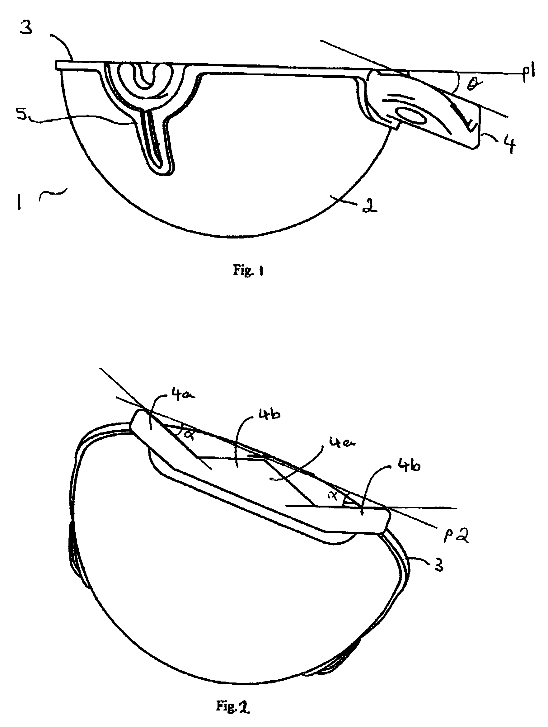
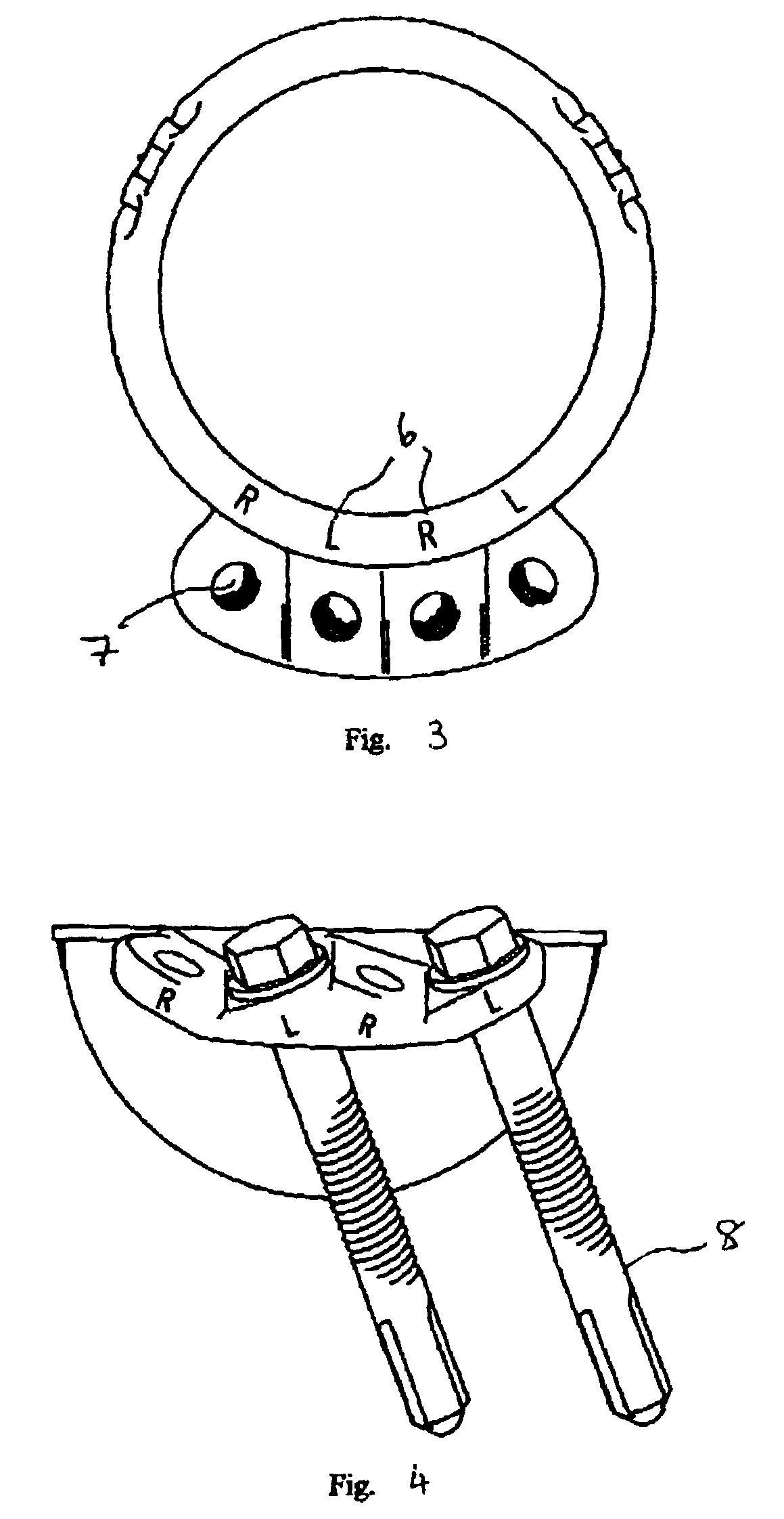
[0053]As illustrated in FIG. 1, the acetabular component of the present invention comprises a cup 1 which has a convex outer surface 2 and a rim 3. A pair of flanges 4 extends form the outer surface 2 at a point adjacent to the rim 3 at an angle θ to the plane p1 of the rim 3. In the illustrated embodiment θ is in the region of 20°. Lugs 5 may be present to prevent rotation and to facilitate the attachment of the cup to a gripping tool used during implantation. An example of a suitable tool can be found in GB2323036.

[0054]Where two pairs of flanges are used which are contiguous an arrangement of the type illustrated in FIG. 2 will be appropriate. Here each flange 4a and 4b is placed at an angle α to the plane p2 which passes through the apex of each flange. In the illustrated arrangement α is 20°. The two flanges making up each pair are at an opposite orientation and corresponding flanges from each pair are parallel. Thus the two flanges 4a are parallel as are the two flanges 4b. Fl...


PUM


Abstract

An acetabular component prosthesis adapted for affixation in a recess in a pelvis, comprising:a cup shell having a generally convex outer surface adapted to be in contact with the bone in use, a generally concave inner surface and a rim;at least one pair of substantially adjacent flanges extending from the outer surface of the cup at a point proximal to the rim of the cup and angled at angle θ downwardly thereto;one flange of the pair being at an equal but opposite angle α to a plane extending across the apex of each of the flanges to the other of the pair; andat least one aperture in each of the pair of flanges through which in use fixation means may be passed to fix the cup into the recess in the pelvis.

Description

FIELD OF THE INVENTION[0001]The present invention relates to a prosthesis. More particularly, it relates to an acetabular component for a hip prosthesis.BACKGROUND OF THE INVENTION[0002]The efficient functioning of the hip joints is extremely important to the well being and mobility of the human body. Each hip joint is comprised by the upper portion of the upper leg bone (femur) which terminates in an offset bony neck surmounted by a ball-headed portion which rotates within a socket, known as the acetabulum, in the pelvis. Diseases such as rheumatoid- and osteo-arthritis can cause erosion of the cartilage lining of the acetabulum so that the ball of the femur and the hip bone rub together causing pain and further erosion. Bone erosion may cause the bones themselves to attempt to compensate for the erosion which may result in the bone being reshaped. This misshapen joint may cause pain and may eventually cease to function altogether.[0003]Operations to replace the hip joint with an a...

Claims


Application Information

Patent Timeline
Patent Type & Authority Patents(United States)
IPC IPC(8): A61F2/32A61B17/86A61F2/00A61F2/30A61F2/34A61F2/46
CPCA61B17/8605A61F2/34A61F2/30771A61F2/4609A61F2002/30576A61F2002/30708A61F2002/30714A61F2002/30769A61F2002/30774A61F2002/30785A61F2002/30787A61F2002/30904A61F2002/3419A61F2002/343A61F2002/3432A61F2250/0084A61F2250/0089A61F2002/3071A61F2002/3417
Inventor WOZENCROFT, ROBERT MICHAELO'HARA, JOHN
Owner FINSBURY DEV
Why Eureka
Try Eureka