Self-powered biosensor

a biosensor and self-powered technology, applied in the field of bioelectronics, can solve problems such as system inaccuracy, and achieve the effect of enhancing the transfer of electrons

Inactive Publication Date: 2009-02-03
YISSUM RES DEV CO OF THE HEBREWUNIVERSITY OF JERUSALEM LTD
View PDF9 Cites 16 Cited by
  • Summary
  • Abstract
  • Description
  • Claims
  • Application Information

AI Technical Summary

Benefits of technology

[0032]The anode, i.e. the working electrode, carries on its surface a layer comprising enzymes capable of catalyzing an oxidation reaction and preferably also an electron mediator group which can enhance the transfer of electrons between the anode and the enzyme.

Problems solved by technology

However, many problems arise in the application of these biosensors, such as the relative sensitivity, selectivity and stability of the sensing device.
In particular, some systems are prone to inaccuracies due to the presence of interfering agents present in the test samples.

Method used


Image

  • Self-powered biosensor
  • Self-powered biosensor
  • Self-powered biosensor

Examples


Embodiment Construction

[0052]The following specific embodiments are intended to illustrate the invention and shall not be construed as limiting its scope.

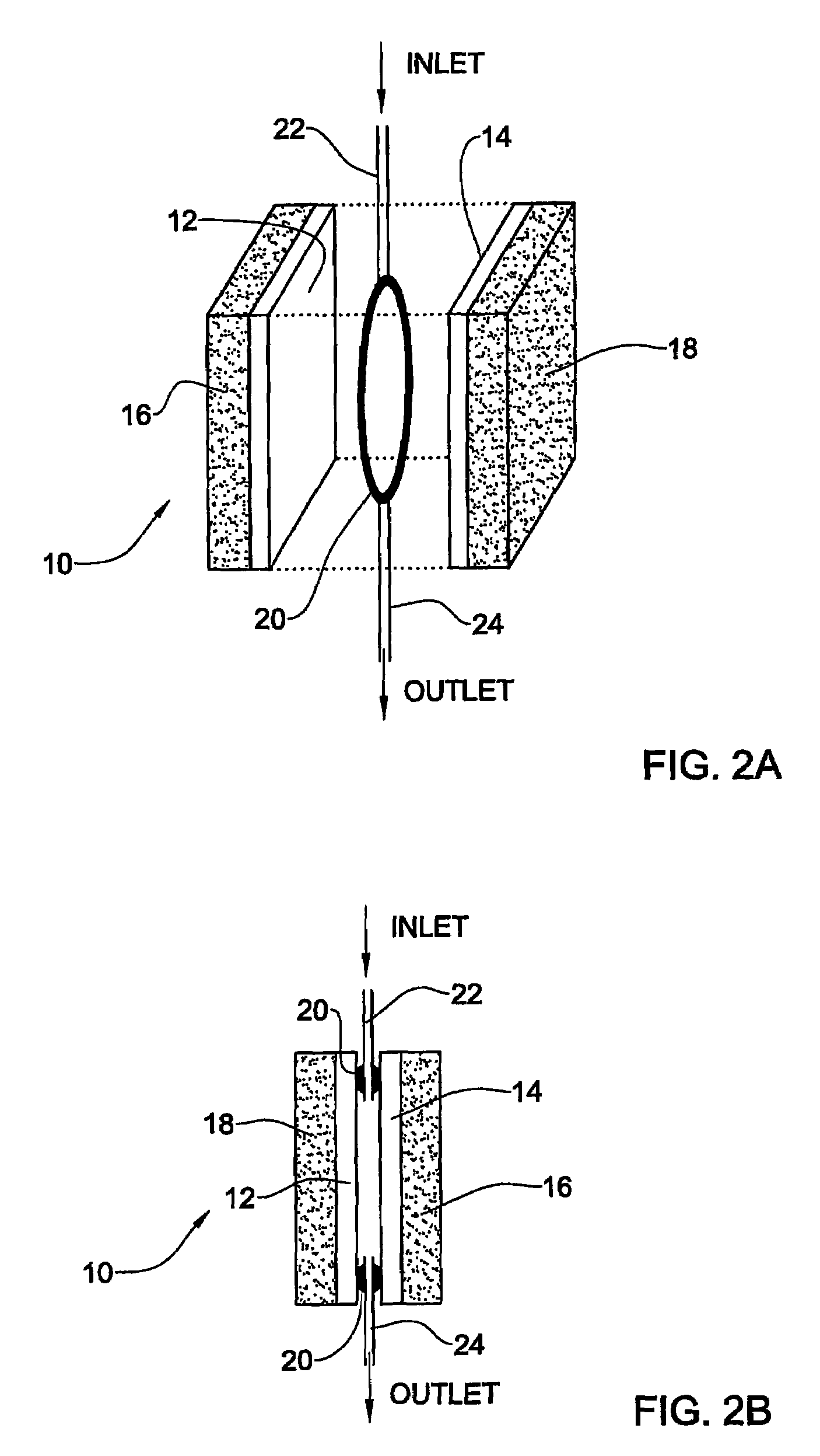
[0053]Reference is being made to FIGS. 2A and 2B that schematically show a simple configuration of a biosensor that may be used in the system of the invention. However, many other assemblies may be fabricated, that are based on the concept of the present invention. Thus, FIG. 2A shows a biosensor 10 (before assembling together all its parts) organized as a flow-injection cell that consists of two enzyme-functionalized Au-electrodes (ca. 0.19 cm active area), acting as anode 12 and cathode 14. Both electrodes are supported on glass plates 16 and 18 and are separated by a rubber O-ring 20 (ca. 2 mm thickness). Needles 22 and 24 implanted into the rubber ring convert the unit into a flow cell, where a liquid medium may flow at a flow rate of 1 mL min−1. The distance between the cathode and the anode is ca. 2 mm. FIG. 2B shows the same device in assembled fo...


PUM

PropertyMeasurementUnit
flow rateaaaaaaaaaa
electricalaaaaaaaaaa
concentrationaaaaaaaaaa

Abstract

The present invention provides a system for the determination of an analyte in a liquid medium. The system comprises a self-powered biosensor and a detector for measuring an electrical signal generated by said biosensor while the analyte is being oxidized or reduced, the biosensor comprising a pair of electrodes, one of the electrodes being an anode and the other a cathode, both of which carry redox enzymes on their surface. An enzyme carried on one of the electrodes can catalyze an oxidation or reduction reaction in which the analyte is oxidized or reduced, respectively, and the other of said pair of electrodes carries on its surface enzymes that can catalyze a reaction in which the oxidizer or the reducer are reduced or oxidized, respectively, in the presence of the analyte.

Description

[0001]This application is a 371 of PCT / IL02 / 00660, filed on Aug. 12, 2002, which claims priority from Israeli application no. 145182, filed on Aug. 29, 2001.FIELD OF THE INVENTION[0002]This invention is in the field of bioelectronics and it relates generally to biosensors useful for measuring the concentration and / or the presence of organic analytes in liquid medium, e.g. medium of environmental, industrial, or clinical origin.PRIOR ART[0003]In the following description reference will be made to several prior art documents shown in the list of references below. The reference will be made by indicating in brackets their number from the list.[0004]1. Willner I. and Katz E., Angew. Chem. Int. Ed., 2000, 39, 1180-1218.[0005]2. (a) Schuhmann, W.; Ohara, T. J.; Schmidt, H. L.; Heller, A. J. Am. Chem. Soc., 1991, 113, 1394-1397. (b) Willner, I.; Riklin, A.; Shoham, B.; Rivenzon, D.; Katz, E. Adv. Mater., 1993, 5, 912-915.[0006]3. (a) Heller, A. J. Phys. Chem. 1992, 96, 3579-3587. (b) Willn...

Claims


Application Information

Patent Timeline
Patent Type & Authority Patents(United States)
IPC IPC(8): G01N27/327A61B5/145A61B5/1477A61B5/1486C12Q1/00G01N27/416H01M8/16
CPCC12Q1/004H01M8/16Y02E60/527Y02E60/50
Inventor WILLNER, ITAMARKATZ, EVGENY
Owner YISSUM RES DEV CO OF THE HEBREWUNIVERSITY OF JERUSALEM LTD
Why Eureka
Try Eureka