High-frequency feed structure antenna apparatus and method of use

a technology of antenna apparatus and high-frequency feed structure, which is applied in the direction of leaky-waveguide antennas, resonance antennas, radiating element structural forms, etc., can solve the problems of polarization, polarization, polarization, and limited bandwidth, and achieves the effect of reducing the number of antennas

Inactive Publication Date: 2009-02-03
UNIV OF SOUTH FLORIDA
View PDF7 Cites 8 Cited by
  • Summary
  • Abstract
  • Description
  • Claims
  • Application Information

AI Technical Summary

Problems solved by technology

However, prior art methods of harvesting high-frequency radiation utilizing rectennas have identified several key problems with the approach.
These problems include impedance matching, rectification, polarization, limited bandwidth and captured power.
Two fundamental physical limitations of the rectennas known in the art are skin effect resistance and very low voltage per antenna element.

Method used


Image

  • High-frequency feed structure antenna apparatus and method of use
  • High-frequency feed structure antenna apparatus and method of use
  • High-frequency feed structure antenna apparatus and method of use

Examples


Embodiment Construction

[0023]The present invention provides a solution to the problem of the MIM rectifier's poor rectification efficiency. One cause of the poor efficiency in a MIM rectifier is the low level of captured electromagnetic radiation by an antenna operating at high frequencies. While the present invention is applicable with high frequency radiation, the present invention is also useful at much lower frequencies, down to the microwave and RF regions of the electromagnetic spectrum.

[0024]An antenna coupled with a high frequency rectifier to harvest electromagnetic energy has numerous applications. Some key features of the present invention include the ability to increase the power at the antenna's terminal as well as decreasing conductor losses in the array feed system by employing a low loss array of high gain antennas. The approach can be employed to increase the efficiency of energy harvesting or as an enhanced detector.

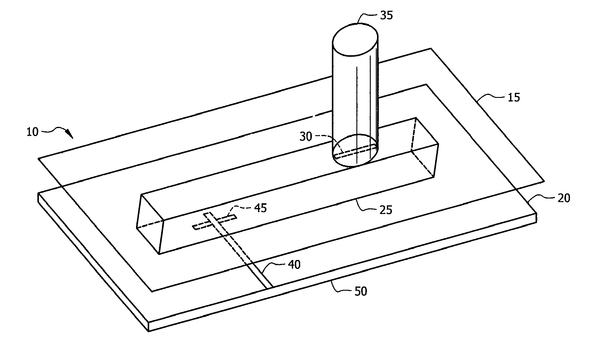
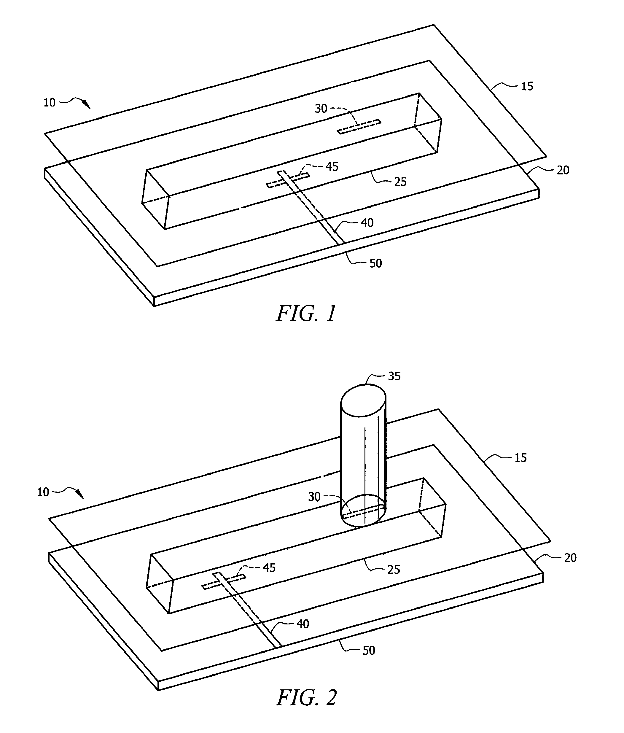
[0025]With reference to FIG. 1, the antenna apparatus 10 in accordance w...


PUM


Abstract

An antenna apparatus for the reception of, and or transmission of, electromagnetic energy, the apparatus including a non-radiating dielectric waveguide aperture coupled to at least one dielectric rod antenna, which is electromagnetically coupled to a transmission line element.

Description

CROSS REFERENCE TO RELATED APPLICATIONS[0001]This application claims priority to currently pending U.S. Provisional Patent Application No. 60 / 720,296, entitled, “A High Frequency Feed Structure Applicable to a Single Antenna or an Array”, filed Sep. 23, 2005 and to currently pending U.S. Provisional Patent Application No. 60 / 720,331, entitled, “A Dual Polarized Feed Structure Applicable to a Single Antenna or an Array”, filed Sep. 23, 2005.STATEMENT OF GOVERNMENT INTEREST[0002]This invention was made with Government support under Grant No. 2106369 LO awarded by the NASA / FSEC. The Government has certain rights in the invention.BACKGROUND OF THE INVENTION[0003]Light energy is characterized by a dual nature both from a quantum point of view as photons and from a wave point of view as randomly polarized electromagnetic radiation with a wavelength between 400 nm and 700 nm. If the ultraviolet and infrared portion of the spectrum is included, the range of wavelengths is extended at both e...

Claims


Application Information

Patent Timeline
Patent Type & Authority Patents(United States)
IPC IPC(8): H01Q1/38H01Q13/10H01Q13/00
CPCH01Q1/248H01Q13/24H01Q13/28
Inventor SAREHRAZ, MOHAMMADBUCKLE, KENNETH A.STEFANAKOS, ELIASWELLER, THOMASGOSWAMI, D. YOGI
Owner UNIV OF SOUTH FLORIDA
Why Eureka
Try Eureka