Reverse link data rate control method in mobile communication system

a mobile communication system and data rate control technology, applied in the field of radio mobile communication system, can solve the problems of unnecessarily consuming transmission power and the entire system may become unstable, and achieve the effect of reducing interferen

Inactive Publication Date: 2009-02-03
LG ELECTRONICS INC
View PDF2 Cites 66 Cited by
  • Summary
  • Abstract
  • Description
  • Claims
  • Application Information

AI Technical Summary

Benefits of technology

[0014]Another object of the present invention is to provide a method of controlling a reverse link data rate, enabling an efficient control of the reverse link data rate of a plurality of R-PDCH subchannels.
[0015]Another object of the present invention is to provide a method of controlling a reverse link data rate, enabling reduced interference between base stations assigning reverse link traffic channels.

Problems solved by technology

Serious interference among the mobile stations of a system results should one of the mobile stations be permitted to operate at a data rate much higher than that of others, and the entire system may become unstable.
Hence, the base station must repetitiously transmit data, which consumes transmission power unnecessarily.

Method used


Image

  • Reverse link data rate control method in mobile communication system
  • Reverse link data rate control method in mobile communication system
  • Reverse link data rate control method in mobile communication system

Examples


first embodiment

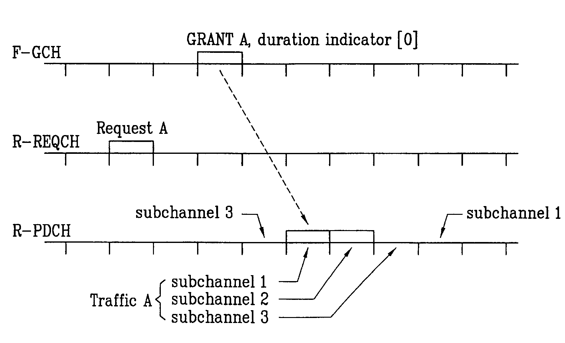
[0034]According to a first preferred embodiment, the duration indicator is contained in a one-bit or two-bit field of the grant message. The one-bit field enables application to traffic occupying three subchannels, as shown in Table 1, and the two-bit field enables application to traffic occupying three or four subchannels, as shown in Table 2. These bit fields, however, are merely exemplary, and the method of the present invention in accordance with the first embodiment may be implemented using a duration indicator of other lengths, and one or more such tables according to the present invention may be stored, for example, in the base station.

[0035]

TABLE 1durationbit field(three subchannel assignment)01 frame12 frames

[0036]

TABLE 2durationdurationbit field(three subchannel assignment)(four subchannel assignment)000 frames0 frames011 frame1 frame102 frames2 frames11X3 frames

[0037]Referring to the above tables, each duration indicator (bit field value) indicates a duration expressed in...

second embodiment

[0045]According to a second preferred embodiment, the duration indicator is contained in a two-bit or three-bit field of the grant message. The two-bit field enables application to traffic occupying three subchannels, as shown in Table 3, and the three-bit field enables application to traffic occupying four subchannels, as shown in Table 4. These bit fields, however, are merely exemplary, and the method of the present invention in accordance with the second embodiment may be implemented using a duration indicator of other lengths, and one or more such tables according to the present invention may be stored, for example, in the base station.

[0046]

TABLE 3rate assignmentrate assignment(subchannel 2,(subchannel 3,bit fieldframe + 1)frame + 2)00not appliednot applied01not appliedapplied10appliednot applied11appliedapplied

[0047]

TABLE 4rate assignmentrate assignmentrate assignment(subchannel 2,(subchannel 3,(subchannel 4,bit fieldframe + 1)frame + 2)frame + 3)000not appliednot appliednot a...


PUM


Abstract

A method of controlling a reverse link data rate, A method of controlling reverse link data rate in a mobile communication system supporting hybrid automatic retransmission request (HARQ) transmission is provided, by which a single grant message is transmitted via a forward grant channel to control a reverse link data rate of a plurality of subchannels of a reverse packet data channel. The method includes steps of generating rate control information for determining a data rate for transmission by a mobile station via a reverse traffic channel; and transmitting to the mobile station a message including the generated rate control information and subchannel information, the message corresponding to a series of subchannel transmissions to which the determined data rate will be applied.

Description

[0001]This application claims the benefit of Korean Patent Application No. 10-2003-0060714 filed on Sep. 1, 2003, which is hereby incorporated by reference.BACKGROUND OF THE INVENTION[0002]1. Field of the Invention[0003]The present invention relates to a radio mobile communication system, and more particularly, to a method of controlling a data rate in transmitting data on reverse link traffic channel in a radio mobile communication system.[0004]2. Discussion of the Related Art[0005]IS-2000 Revision D provides for a mobile communication system enabling packet data transmission to a base station on a reverse-link traffic channel, namely, a reverse packet data channel or R-PDCH, but a mobile station cannot autonomously determine a data transmission rate of a reverse link channel. Serious interference among the mobile stations of a system results should one of the mobile stations be permitted to operate at a data rate much higher than that of others, and the entire system may become un...

Claims


Application Information

Patent Timeline
Patent Type & Authority Patents(United States)
IPC IPC(8): H04J1/16H04L1/00H04B7/005H04L1/18H04L12/56H04W28/22
CPCH04W28/22H04L1/0002H04L1/1812H04W52/0206H04W28/04H04W48/08H04L1/0025Y02B60/50Y02D30/70H04B7/005
Inventor SEOL, JEE WOONG
Owner LG ELECTRONICS INC
Why Eureka
Try Eureka