Low-power cache system and method

a cache system and low-power technology, applied in the field of memory system design, can solve the problems of affecting the performance of the cache architecture, and consuming a large amount of system power, so as to reduce power dissipation, increase modularity, and provide scalable associativity.

Inactive Publication Date: 2009-02-03
AVAGO TECH WIRELESS IP SINGAPORE PTE
View PDF8 Cites 11 Cited by
  • Summary
  • Abstract
  • Description
  • Claims
  • Application Information

AI Technical Summary

Benefits of technology

[0010]Advantageously, the cache architecture in the present invention reduces power dissipation, increases modularity, and provides scalable associativity. The complexity of the cache architecture is also simplified by sharing circuits among tag and data arrays. Moreover, additional associativity can be added to the cache architecture without incurring additional costs.

Problems solved by technology

In a mobile society at the start of a new millennium, a challenge in designing a compact or handheld device is to extend the battery power duration after a charge-up.
A cache is an integral part of a computing system but draws a significant amount of system power.
When additional associativities are stacked over existing associativities, cache architecture draws an even greater amount of power as well as causing potential timing problems.

Method used


Image

  • Low-power cache system and method
  • Low-power cache system and method
  • Low-power cache system and method

Examples


Embodiment Construction

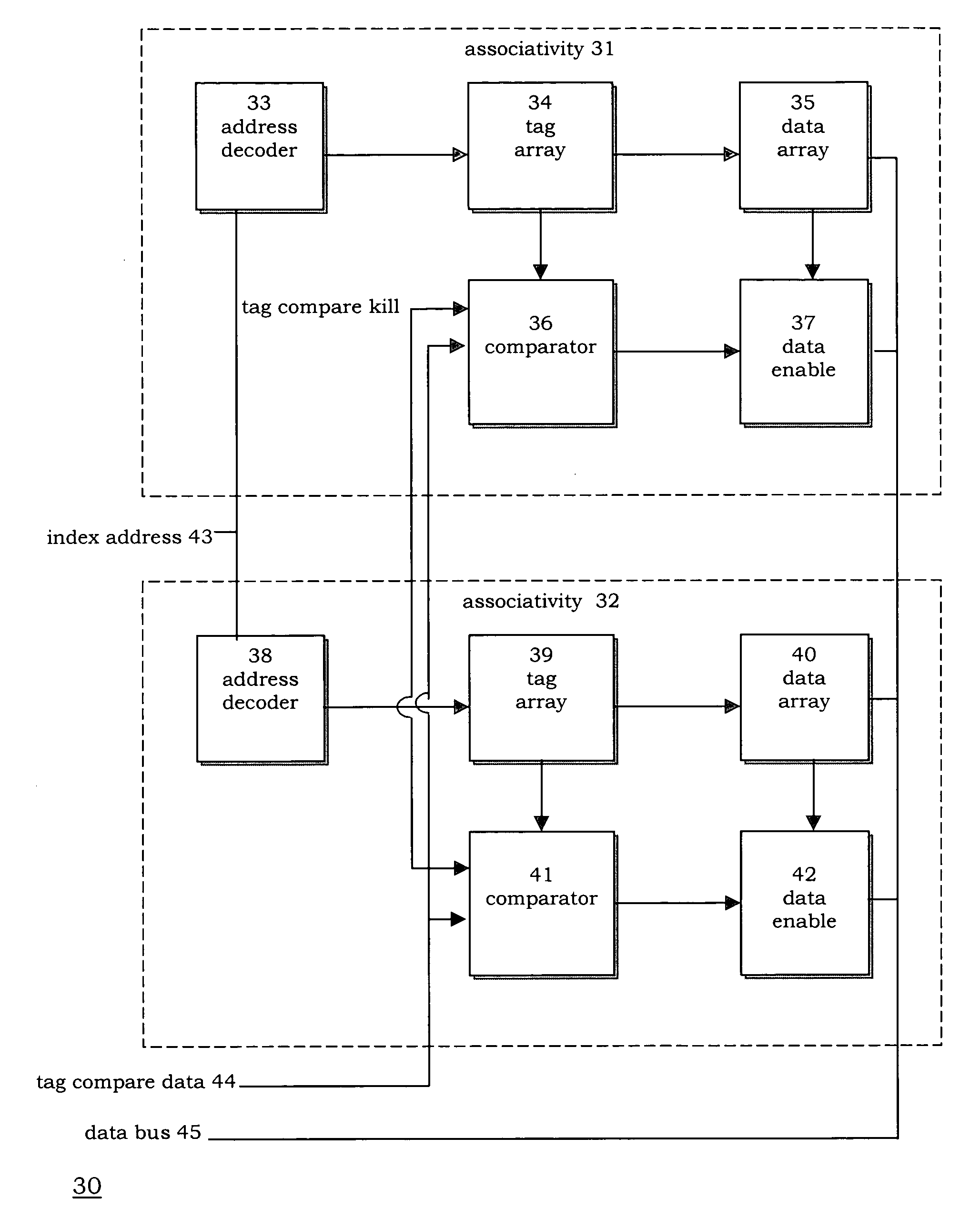
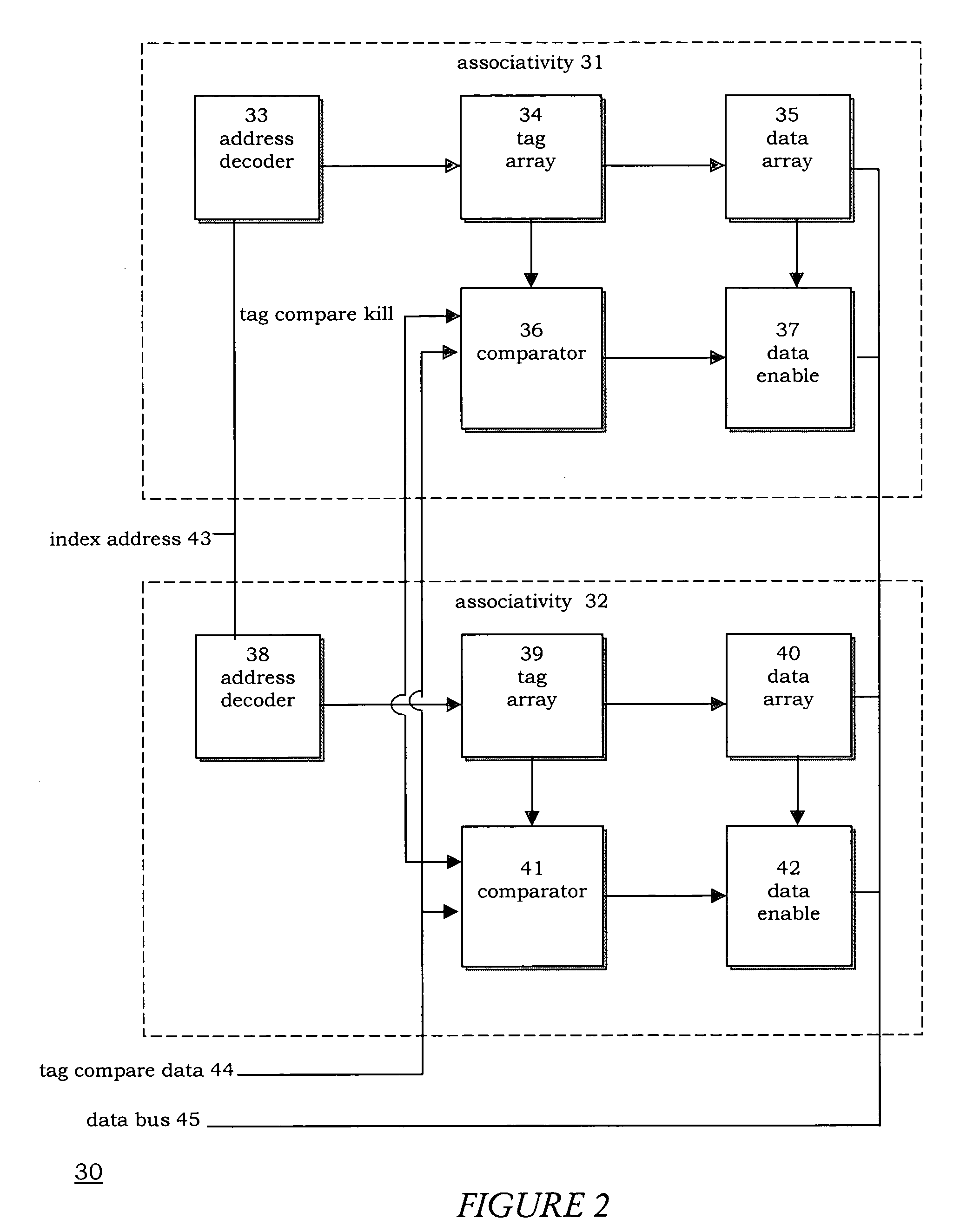
[0015]FIG. 2 is a block diagram illustrating a cache pipelined architecture 30, with an associativity 31, and an associativity 32. An address decoder 33 is shared by a tag array 34 and data array 35 in associativity 31. Similarly, a common address decoder 38 is used in associativity 32 for decoding with a tag array 39, and a data array 40.

[0016]Address decoder 33 serves to decode the incoming index address 43 in associativity 31. Initially, tag array 34 is powered-up without supplying power to data array 35. A comparator 36 compares the tag from tag array 34 with a tag compare data 44. Comparator 36 generates an output signal that enables or disables a data enable 37 for powering up or not powering up data array 35. When data array 35 is powered-up, and there is a tag hit, data enable 37 enables output to place data on a data bus 45.

[0017]Similar type of flow is generated through associativity 32. Address decoder 38 decodes the incoming index address 43. Initially, tag array 39 is p...


PUM


Abstract

The invention provides a cache architecture that selectively powered-up a portion of data array in a pipelined cache architecture. A tag array is first powered-up, but the data array is not powered-up during this time, to determine whether there is a tag hit from the decoded index address comparing to the tag compare data. If there is a tag hit, during a later time, a data array is then powered-up at that time to enable a cache line which corresponds with the tag hit for placing onto a data bus. The power consumed by the tag represents a fraction of the power consumed by the data array. A significant power is conserved during the time in which the tag array is assessing whether a tag hit occurs while the data array is not powered-on at this point.

Description

BACKGROUND INFORMATION[0001]1. Field of the Invention[0002]The invention relates to integrated circuits, and particularly to memory system designs of a cache architecture.[0003]2. Description of Related Art[0004]In a mobile society at the start of a new millennium, a challenge in designing a compact or handheld device is to extend the battery power duration after a charge-up. A cache is an integral part of a computing system but draws a significant amount of system power. A design trend in the past has a dominant focus on finding new ways to increase the speed of a computing system. However, prolonging a battery power has become a primary focus in the design of wireless and mobile devices.[0005]A cache refers to a storage architecture in integrated circuits and software where the most commonly used data is tagged and stored for quick retrieval. A principle usage of a cache is to speed-up processing of information of an application program. A cache tags a piece of data or information...

Claims


Application Information

Patent Timeline
Patent Type & Authority Patents(United States)
IPC IPC(8): G06F1/32G06F12/00
CPCG06F1/3203G06F1/3275G06F12/0802Y02B60/1228G06F2212/1028Y02B60/1225Y02D10/00
Inventor GUPTA, MAYANKPAK, EDWARD T.VILLAGOMEZ, JAVIERVOSS, PETER H.
Owner AVAGO TECH WIRELESS IP SINGAPORE PTE
Why Eureka
Try Eureka