Supercharge Your Innovation With Domain-Expert AI Agents!

Cryogenic air separation method with temperature controlled condensed feed air

a condensed feed and cryogenic air technology, applied in the field can solve the problem of very energy-intensive process of cryogenic air separation

Inactive Publication Date: 2009-02-10
PRAXAIR TECH INC
View PDF10 Cites 0 Cited by
  • Summary
  • Abstract
  • Description
  • Claims
  • Application Information

AI Technical Summary

Benefits of technology

This method enhances the utilization of refrigeration by optimizing the separation process, reducing energy consumption and improving the efficiency of cryogenic air separation.

Problems solved by technology

Cryogenic air separation is a very energy intensive process because of the need to generate low temperature refrigeration to drive the process.

Method used


Image

  • Cryogenic air separation method with temperature controlled condensed feed air
  • Cryogenic air separation method with temperature controlled condensed feed air
  • Cryogenic air separation method with temperature controlled condensed feed air

Examples


Embodiment Construction

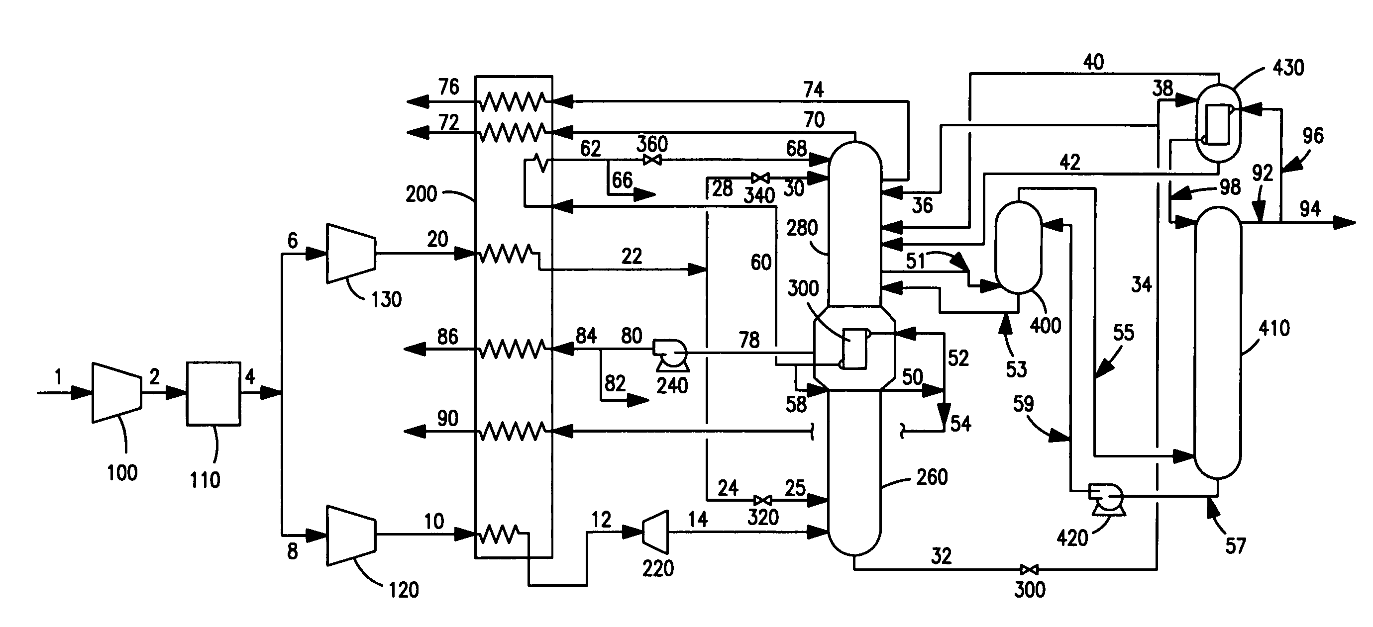
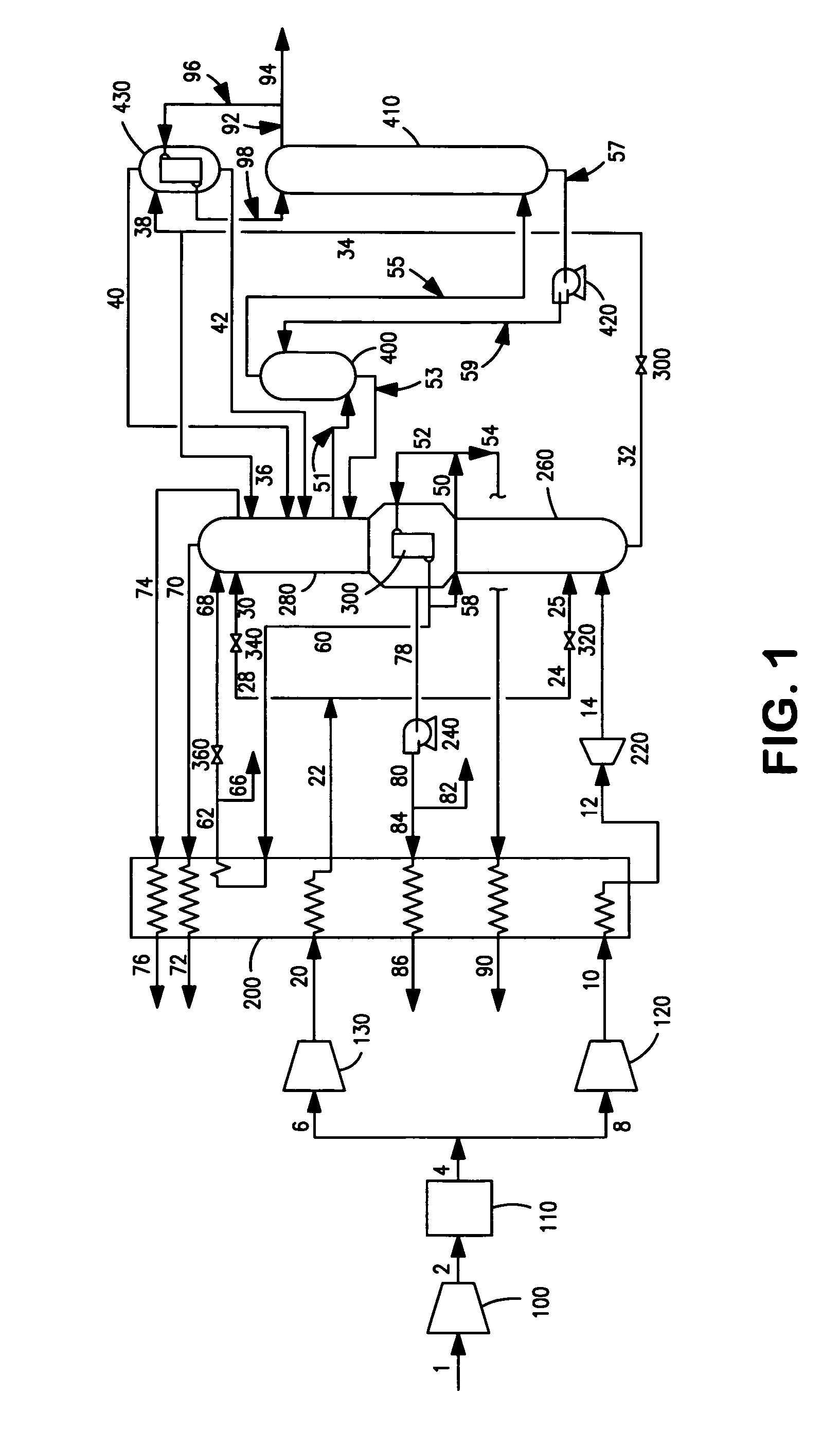
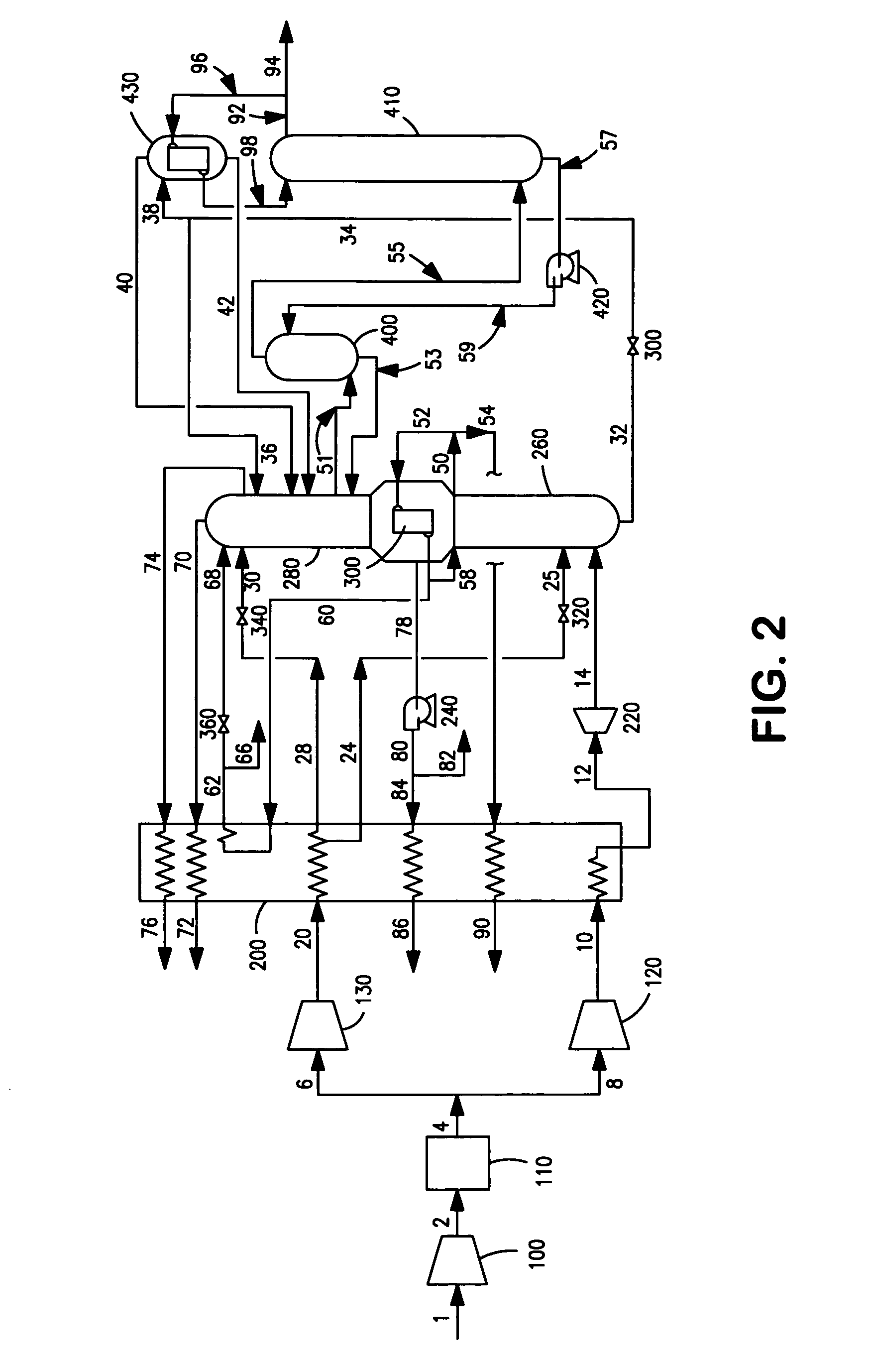
[0018]The invention will be described in greater detail with reference to the Drawings. The cryogenic air separation plant illustrated in the Drawings comprises a double column, having a higher pressure column 260 and a lower pressure column 280, a low ratio argon column 400, and a super-staged argon column 410.

[0019]Referring now to FIG. 1, feed air 1 is compressed in compressor 100 and compressed feed air stream 2 is cleaned of high boiling impurities in purifier 110. Resulting cleaned, compressed feed air 4 is divided into stream 6 and stream 8. Feed air stream 6 is further compressed in compressor 130 and resulting feed air stream 20 is passed into main heat exchanger 200 wherein it is condensed by indirect heat exchange with return streams such as pumped liquid oxygen, and from which it emerges as condensed feed air stream 22 having a temperature generally within the range of from 92K to 105K, preferably within the range of from 93.5K to 102K.

[0020]Condensed feed air 22 is divi...


PUM


Abstract

A method for the cryogenic separation of air having defined temperatures for condensed feed air passed into a double column system relative to liquid oxygen and preferably to shelf vapor, and wherein kettle liquid is not subcooled from the higher pressure column to the lower pressure column.

Description

TECHNICAL FIELD[0001]This invention relates generally to cryogenic air separation and, more particularly, to cryogenic air separation employing a double column and wherein at least some feed air is condensed prior to passage into one or both of the columns.BACKGROUND ART[0002]Cryogenic air separation is a very energy intensive process because of the need to generate low temperature refrigeration to drive the process. Accordingly, any method which improves the utilization of the available refrigeration in carrying out cryogenic air separation would be very desirable.SUMMARY OF THE INVENTION[0003]A method for carrying out cryogenic air separation employing a double column having a higher pressure column and a lower pressure column comprising:[0004](A) condensing feed air, passing the condensed feed air into the higher pressure column, and separating feed air within the higher pressure column by cryogenic rectification to produce nitrogen-enriched vapor and oxygen-enriched liquid;[0005...

Claims


Application Information

Patent Timeline
Patent Type & Authority Patents(United States)
IPC IPC(8): F25J3/00
CPCF25J3/0409F25J3/04175F25J3/0423F25J3/04236F25J3/04296F25J3/04412F25J3/04678F25J3/04703F25J2235/58
Inventor WEBER, JOSEPH ALFREDAHMED, M. MUSHTAQSKARE, TODD ALANPROSSER, NEIL MARK
Owner PRAXAIR TECH INC
Features
  • R&D
  • Intellectual Property
  • Life Sciences
  • Materials
  • Tech Scout
  • Unparalleled Data Quality
  • Higher Quality Content
  • 60% Fewer Hallucinations
Learn More