Method and equipment for the protection of power systems against geomagnetically induced currents

a technology of geomagnetism and power system, applied in the direction of transformer/inductance details, circuit arrangements, electrical equipment, etc., can solve the problems of transformers consuming high magnetizing currents, transformers entering magnetic saturation, disturbances in the transmission and distribution of electrical energy,

Inactive Publication Date: 2009-02-10
FORSKARPATENT I SYD AB
View PDF17 Cites 26 Cited by
  • Summary
  • Abstract
  • Description
  • Claims
  • Application Information

AI Technical Summary

Benefits of technology

[0017]This invention relates to a DC-diverter, which shunts the direct current from the sensitive power transformers to an alternative path or to alternative paths. The DC-diverter is designed to withstand the direct current caused by geomagnetic storms and the alternating currents associated with earth faults near the bus where the DC-diverter is connected. In a substation with several power transformers, one DC-diverter can eliminate the need to install several neutral point devices and avoid installing several transformers that are designed to withstand direct current.
[0021]Another aspect of the invention relates to a DC-diverter to carry out the method of above, consisting of a magnetic core structure having three phase legs, each leg provided with a primary diverter winding and each provided with a diverter compensation winding and having a filter connected to the neutral point of the three-phase diverter to reduce the harmonics, to eliminate flow of these through the compensation winding, and whereby the diverter has an impedance lower than that of a component diverted from.

Problems solved by technology

The direct current gives rise to unilateral magnetization levels of any transformer in the system, which may cause the core of the transformer to enter magnetic saturation.
This leads to the transformer consuming high magnetizing currents, thus being disconnected, normally by means of a protecting system, which releases the transformer from the system.
When a transformer is disconnected, released, from the system, this will of course lead to disturbances in the transmission and distribution of electrical energy.
Geomagnetically induced currents (GICs) may, as mentioned above, damage power transformers because of half-cycle saturation of the core and heat developed in iron parts of the transformer.
The heat dissipation may be so high that the transformer oil starts to boil after a short while.
One disadvantage with such devices is that the transformer may have graded insulation and the insulation level at the neutral may be too low to withstand the voltage at earth-faults near of the busbar where the transformer is connected.
Another disadvantage with such neutral point devices is that they force the direct current to flow through other transformers and makes it necessary to equip also them with neutral point devices.
This causes the power frequency (50 Hz or 60 Hz) AC magnetic flux to spread out through the windings and structural members of the transformer producing eddy currents that can cause hotspots, which may severely damage the transformer.
These increased harmonics cause incorrect operation of protective relays and may cause disconnection of power lines.
The increased reactive power demand accompanied with unwanted operation of protective relays may cause a collapse of power systems.
The half-cycle saturated transformer draws a severely distorted current from the power system and distorts the waveform of the voltage on the associated busbar.
The general voltage depression, the distorted current and voltage waveforms, and the harmonics may cause incorrect operation of the protection system.

Method used


Image

  • Method and equipment for the protection of power systems against geomagnetically induced currents
  • Method and equipment for the protection of power systems against geomagnetically induced currents
  • Method and equipment for the protection of power systems against geomagnetically induced currents

Examples


Embodiment Construction

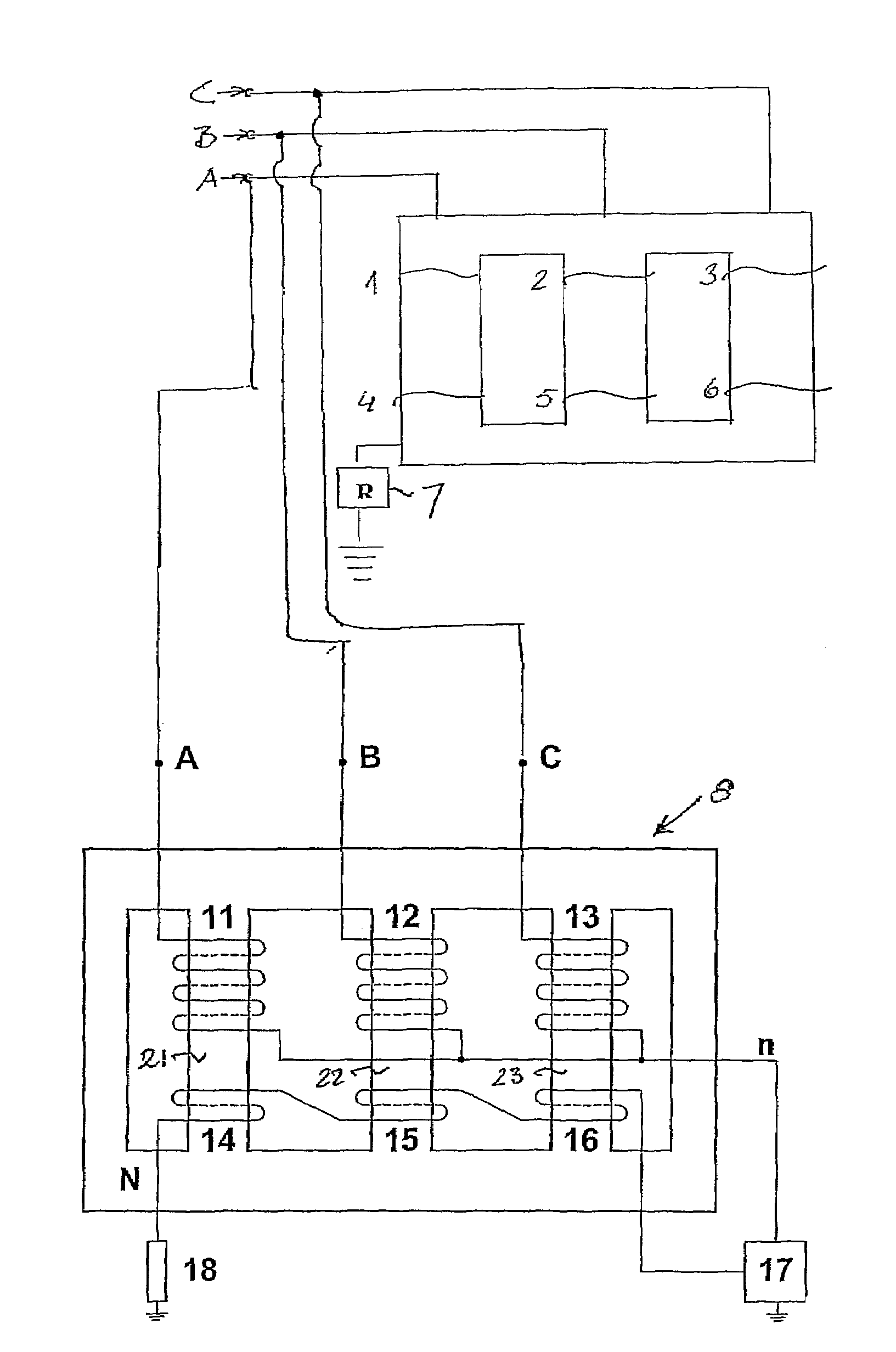
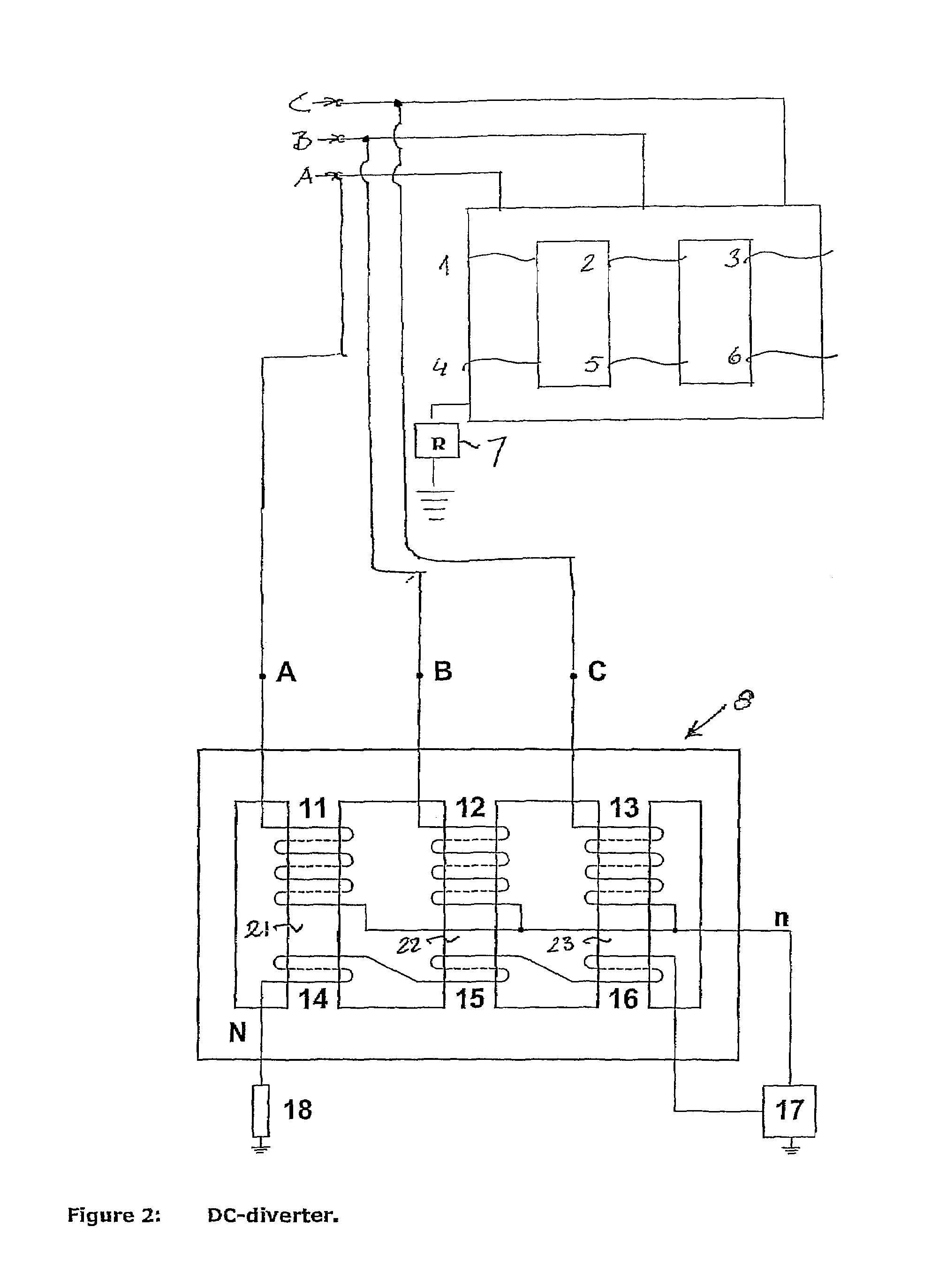
[0026]FIG. 2 shows a 3-phase power line, with phase lines A, B, and C, respectively, having at its end a three-phase transformer reducing the voltage from 400 kV to 50 kV. However, any primary voltage may be used such as 765, 500, 400, 345, or 220 kV, while the secondary voltage may be 110, 70, 50, 40, 30, 20, 10 or 6 kV.

[0027]The transformer may take any physical form used in the art, such as a three-legged one, a four-legged one, or a five-legged one, a temple designed one, a modified temple designed one, or simply being three one-phase transformers connected in a suitable manner. FIG. 2 is a schematic view showing three primary windings, 1, 2, and 3, and three secondary windings 4, 5, and 6. Between the earth point and earth there is a resistance 7, suitably less than 10 ohms, to provide an impedance higher than for a DC-diverter, generally denoted 8.

[0028]The DC-diverter comprises, in the embodiment shown, a basic transformer magnetic core structure having three phase legs 21, 2...


PUM

PropertyMeasurementUnit
frequencyaaaaaaaaaa
frequencyaaaaaaaaaa
frequencyaaaaaaaaaa

Abstract

The present invention relates to a method for protection of power transformers and other power system components, which are vulnerable to geomagnetically induced currents, which comprises feeding from an overhead line / s or cable conductor / s one or more DC-diverter consisting of primary diverter windings and compensation windings applied on a respective magnetic core leg, which diverter is connected to critical busses, and diverting “quasi” direct current flowing on the overhead lines or cable conductors as a result of the earth surface potential gradients caused by geomagnetically induced currents, as well as a DC diverter to carry out the method.

Description

PRIORITY INFORMATION[0001]This application is a continuation of International Application Ser. No. PCT / SE2005 / 000659 filed on May 4, 2005 which claims priority to Swedish Application No. 0401193-8 filed May 10, 2004, both of which are incorporated herein by reference in their entirety.TECHNICAL FIELD[0002]Geomagnetic disturbances pose hazards to several man-made systems because the Geomagnetically induced currents (GICs) flow in electrically conducting systems, such as power transmission networks, oil and gas pipelines, telecommunication cables and railway equipment.BACKGROUND OF THE INVENTION[0003]The primary task of a power transformer is to act as an electric “gear box” and sometimes to create a galvanic isolation, allowing electric energy to flow from one electrical ● system to another. The electrical systems interconnected with a transformer usually have different voltages but always the same frequency. The power transformer, in its simplest form, comprises generally at least t...

Claims


Application Information

Patent Timeline
Patent Type & Authority Patents(United States)
IPC IPC(8): H02H7/04H01F27/34H01F27/38H01F30/12H02H9/00H02J
CPCH01F27/38H01F27/34H01F27/345H01F30/12H02H9/005
Inventor A F KLERCKER ALAKULA, MATSLINDHAL, STURE
Owner FORSKARPATENT I SYD AB
Why Eureka
Try Eureka