Apparatus for neuromuscular measurement and control

a neuromuscular and apparatus technology, applied in the field of apparatus for neuromuscular measurement and control, can solve the problems of only operating voltage clamps, not being reconfigured to operate as dynamic clamps, and system not providing sufficient speed and flexibility

Inactive Publication Date: 2009-02-10
BOARD OF GOVERNORS FOR HIGHER EDUCATION STATE OF RHODE ISLAND & PROVIDENCE PLANTATIONS
View PDF2 Cites 4 Cited by
  • Summary
  • Abstract
  • Description
  • Claims
  • Application Information

AI Technical Summary

Benefits of technology

[0010]Advantageously, digital feedback control provides programmability, capability for dynamic changes of clamping modes, hardware simplification, and integration of multi-channel clamping systems.
[0011]The digital signal processor in the feedback loop provides programmability in the control algorithm. The traditional voltage clamp, current clamp, and dynamic clamp have been accomplished by use of different, separate systems. The device of the present invention accomplishes all clamping needs in a single integrated system.

Problems solved by technology

Such a system does not provide sufficient speed and flexibility to be a general instrument for neuroscience research.
However, prior art voltage, current and dynamic clamps have been dedicated, non-configurable devices that perform only their respective voltage, current or dynamic clamp functions, respectively.
That is, prior art voltage clamps would only operate as a voltage clamp, and could not be reconfigured to operate as a dynamic clamp, and visa versa.

Method used


Image

  • Apparatus for neuromuscular measurement and control
  • Apparatus for neuromuscular measurement and control
  • Apparatus for neuromuscular measurement and control

Examples


first embodiment

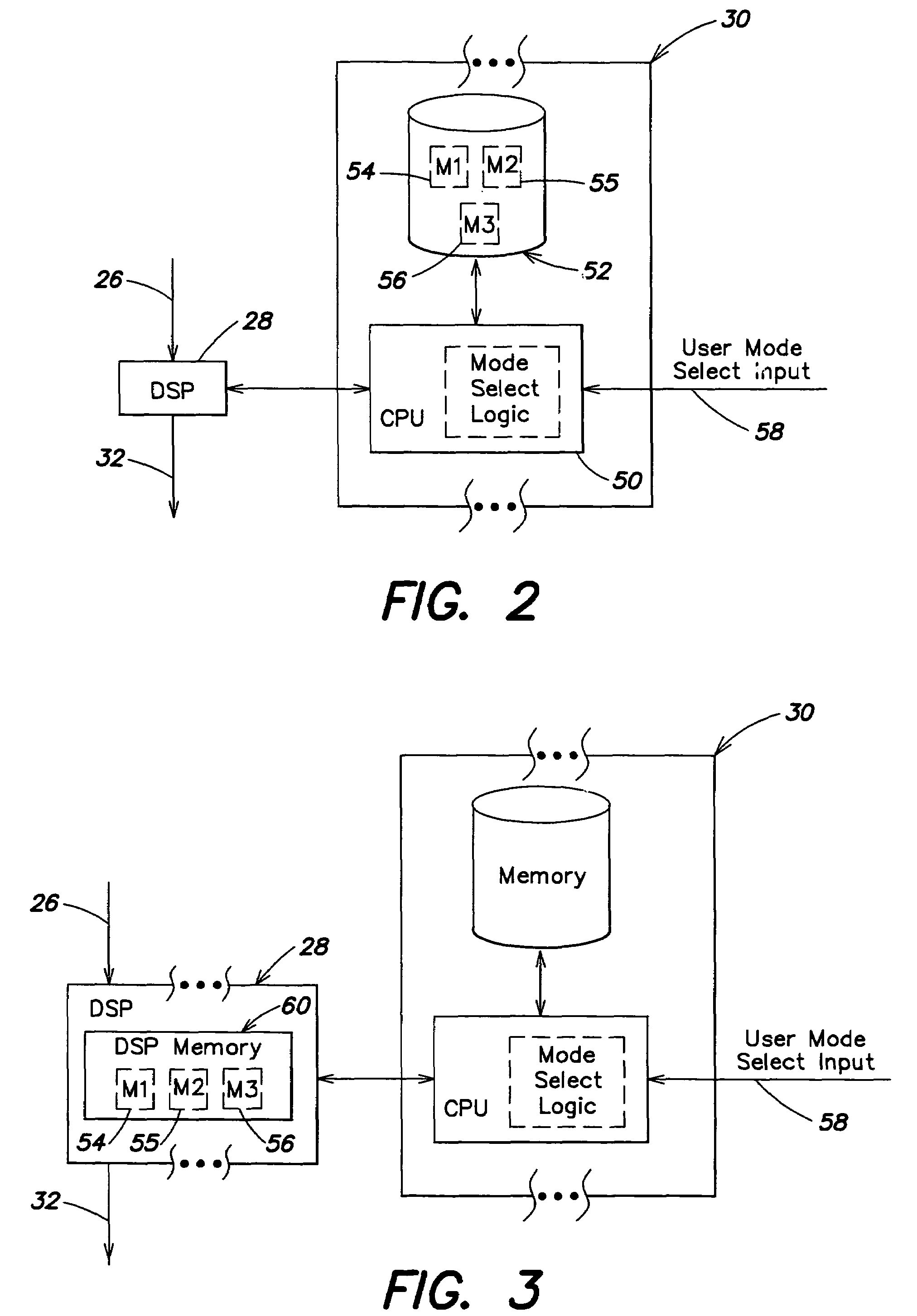
[0027]FIG. 2 is a simplified functional block diagram illustration of the user configurable clamp of FIG. 1, wherein executable program instructions associated with the various operating modes of the user configurable clamp are selectively downloaded to the DSP 28 in response to a mode selection. The PC 30 includes a CPU 50, and a memory device 52 that includes a plurality of DSP executable software routines 54-56. The PC 30 receives a clamp mode input signal on a line 58 from a user (e.g., a via a keyboard or other input device), and in response the CPU 50 selects the DSP executable software routine 54-56 associated with the mode specified by the clamp mode input signal on the line 58. For example, the DSP executable software routines 54-56 may be associated with the voltage clamp mode, the current clamp mode and the dynamic clamp mode, respectively. Once the selected routine 54-56 is downloaded to the DSP 28, the DSP begins operating in the selected mode by executing the downloade...

second embodiment

[0028]FIG. 3 is a functional block diagram illustration of the user configurable clamp of FIG. 1, wherein executable program instructions associated with the various operating modes of the user configurable clamp are stored in the DSP 28 and selectively executed in response to a mode selection. In this embodiment, DSP memory 60 includes the various DSP executable software routines 54-56. The PC 30 receives the clamp mode select signal on the line 58 and provides a signal indicative thereof to the DSP 28, which then selects from the DSP executable software routine 54-56 for the executable routine associated with the selected mode. The DSP then begins operating in the selected mode by executing the downloaded routine.

[0029]FIG. 4 is a functional block diagram illustration a user configurable clamp 100 that includes a single lead 102 connected to the tissue (not shown). This embodiment is substantially the same as the embodiment illustrated in FIG. 1, with the principal exception that ...


PUM


Abstract

A dynamically configurable clamping device for applying a desired electrical current to a tissue membrane includes an input lead electrically connected to the tissue membrane to provide a sensed signal indicative of voltage across the membrane. An input circuit includes an analog-to-digital converter, and is responsive to the sensed signal and provides a digitized signal indicative of the sensed signal. A digital signal processor executes selected program instructions to operate in a selected one of (i) a voltage clamp mode, (ii) a current clamp mode or (iii) a dynamic clamp mode based upon the state of a mode selection signal indicative of the selected operating mode. The digital signal processor provides a digital current command signal indicative of the current to be applied to the tissue membrane. An output circuit receives the digital current command signal, and generates a current signal indicative thereof. An output lead receives and applies the current signal to the tissue membrane. Digital feedback control is advantageous over the traditional systems by providing programmability, capability for dynamic changes of clamping modes, hardware simplification, and integration of multi-channel clamping systems. The digital signal processor in the feedback loop provides programmability in the control algorithm.

Description

PRIORITY DATA[0001]This application is a continuation of International Patent Application No. PCT / US03 / 10317, filed Apr. 4, 2003, which claims the benefit of U.S. Provisional Application No. 60 / 369,964 filed Apr. 4, 2002, and hereby incorporated by reference.BACKGROUND OF THE INVENTION[0002]The present invention relates to the field of devices to study the electrophysiology of nerve and muscle tissues, and in particular to a dynamically configurable clamp device used to measure and control nerve and muscle tissues.[0003]A neuroscience laboratory is generally equipped with at least one voltage clamp system to study the electrophysiology of nerve and muscle tissues. Current-voltage relations across excitable membranes are time varying, nonlinear, and spatially distributive. By clamping the membrane potential to a step function, the voltage clamp system momentarily achieves spatial coherence and voltage invariance. The current injected back into the cell for maintaining a constant memb...

Claims


Application Information

Patent Timeline
Patent Type & Authority Patents(United States)
IPC IPC(8): A61N1/00A61B5/05A61N1/32
CPCA61B5/05A61N1/32A61B5/4041A61B5/4047
Inventor SUN, YINGWU, JIANGCOLLIS, LEON P.HILL, ROBERT B.
Owner BOARD OF GOVERNORS FOR HIGHER EDUCATION STATE OF RHODE ISLAND & PROVIDENCE PLANTATIONS
Why Eureka
Try Eureka