
Detector of low levels of gas pressure and flow

a technology of gas pressure and flow, applied in the direction of fluid pressure measurement by thermal means, measurement devices, instruments, etc., can solve the problems of increased cost, difficult monitoring of very low air flow rate, and sensitive pressure detectors that in many cases may be too complex or too expensive or not sufficiently accura

Active Publication Date: 2009-02-17
CLEAN ALERT INNOVATIONS LLC
View PDF11 Cites 14 Cited by
  • Summary
  • Abstract
  • Description
  • Claims
  • Application Information

AI Technical Summary

Benefits of technology

This solution provides accurate, inexpensive, and simple monitoring of gas flow rates and pressure changes over a broad temperature range, enabling effective detection of air filter clogging and small pressure variations, suitable for HVAC systems, security systems, and fuel burners.

Problems solved by technology

One problem in using the indirect method is a difficulty in monitoring very low air flow rates which may be as low as few mm of H2O.
This requires very sensitive pressure detectors that in many cases may be too complex or too expensive or not sufficiently accurate.
On the other hand, the direct sensors may require a direct placement into the flow duct that may increase cost and make maintenance more difficult.

Method used


Image

  • Detector of low levels of gas pressure and flow
  • Detector of low levels of gas pressure and flow
  • Detector of low levels of gas pressure and flow

Examples


Embodiment Construction

[0038]As it follows from Eq. (1), a differential air pressure can be computed from the air flow rate from the following formula:

[0039]P1-2=v1-22⁢kd2⁢⁢g,(2)

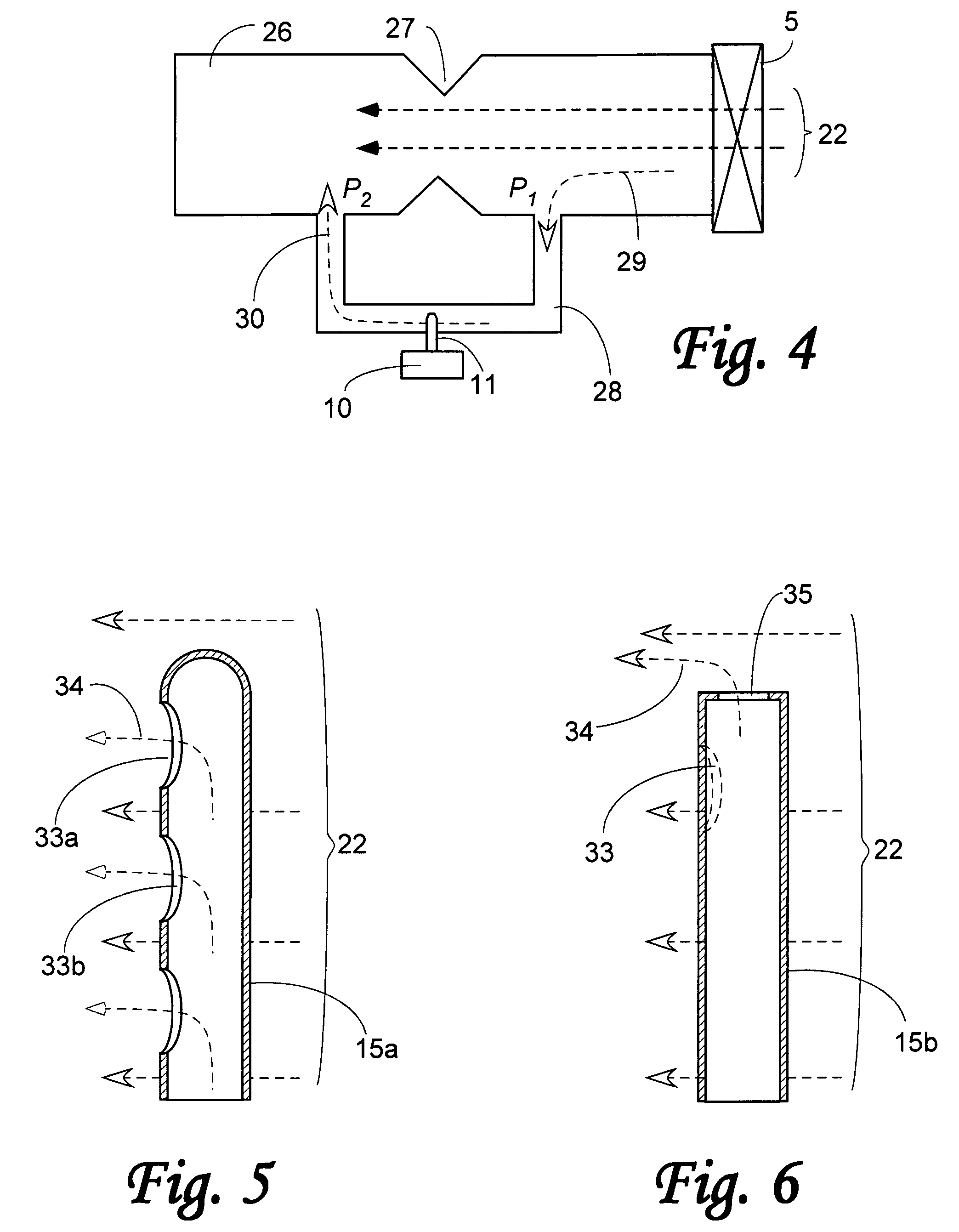
and therefore, a differential pressure measurement may be substituted by measurement of the air flow as shown in a general diagram of FIG. 4. The air duct 26 contains an air flow restriction 27 that can be caused, for example, by an air duct geometry, the air filter, or other components. The air flow 22 is produced by the air blower 5. A bypass tube 28 circumvents the flow restriction 27, thus diverting a small portion of air flow 29 to go through the bypass tube 28 and exit as flow 30 at the other side of restriction 27. The respective ends of the bypass tube 28 are exposed to two air pressures, P1 and P2. An air flow monitor 10 is installed at the bypass tube 28 with its flow sensor 11 being exposed to the interior of the bypass tube 28. Since the airflow 30 inside the bypass tube 28 related to a differential pressure P1-2=P1−P2...


PUM


Abstract

A detector for monitoring the low levels of differential pressures and the rate of mass flow rate of gas (air, e.g.) in a duct. The sensor's temperature is maintained at a constant gradient above temperature of the flowing gas, typically 4-7° C. higher. The detector consists of two thermally decoupled sensors—one is the air temperature sensor and the other is a temperature sensor coupled to a heater. The sensors are connected to an electronic servo circuit that controls electric power supplied to the heater. The sensors are positioned outside of the air duct and coupled to the duct via a relatively thin sensing tube protruding inside the duct. The end of the tube has an opening facing downstream of the gas flow, thus being exposed to a static gas pressure. The detector can be employed in fuel burners of the HVAC systems, internal combustion engines, medical equipment to control flow of anesthetic gases, in the security systems to monitor minute changes in air pressure resulted from opening and closing of doors and windows in a protected facility.

Description

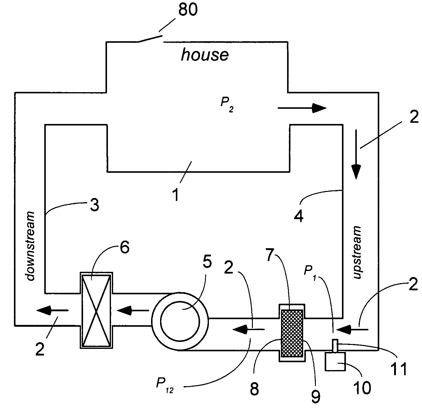
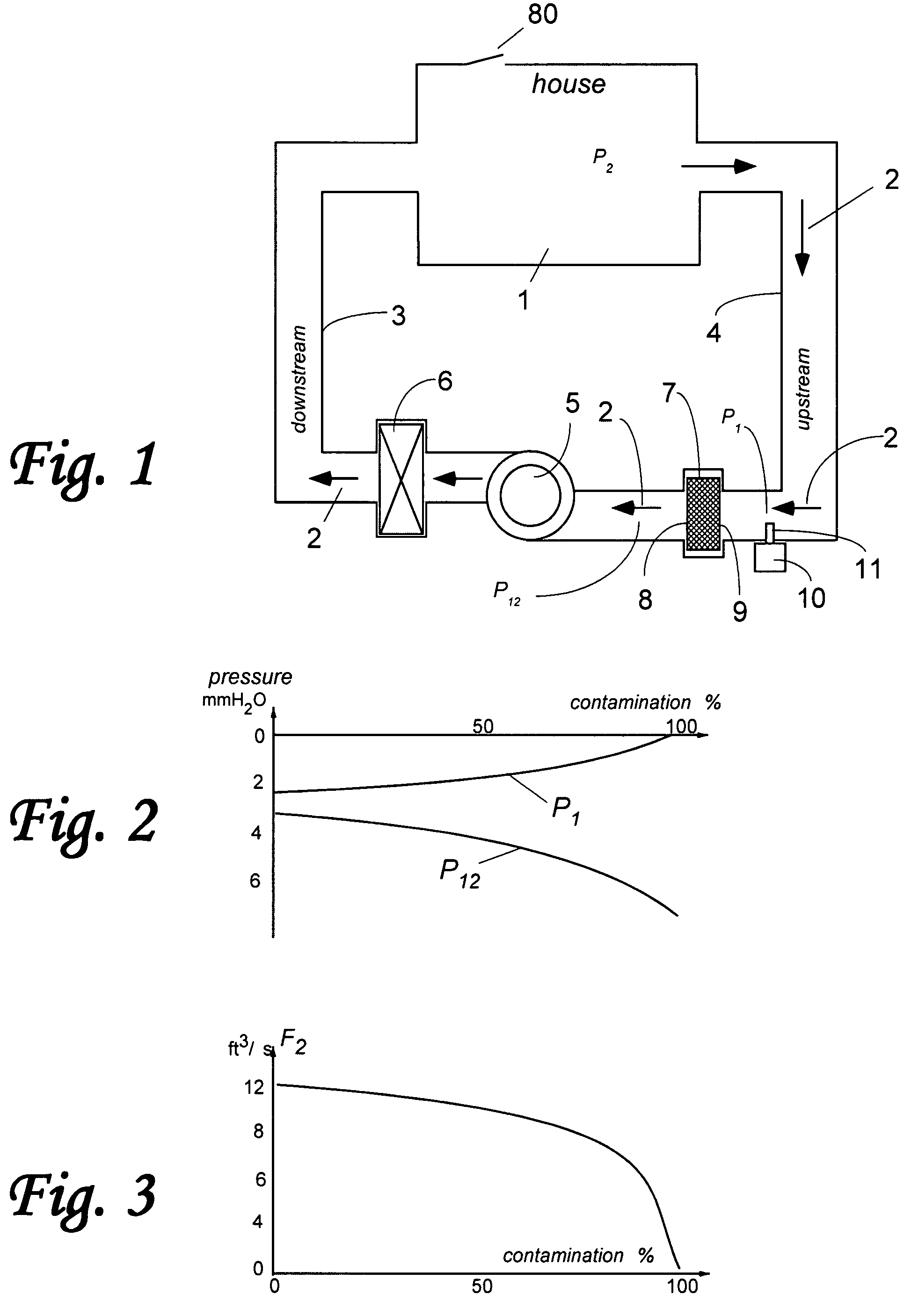
[0001]The present invention relates generally to devices for measuring and monitoring differential gas pressure and relatively low rates of gas flow. It is based on U.S. Provisional Patent Application No. 60 / 841,663 filed on Sep. 1, 2006.BACKGROUND OF INVENTION[0002]In many types of equipment that use movements of air or other gases, measuring the mass flow rate of the gas and / or static gas pressure is very important. An example is a HVAC system of a residential dwelling that incorporates an air filter. Typically, mass of gas (air, in particular) is driven through the dwelling or machinery by means of a forced convection. The purpose of the air filters is to remove airborne contaminants that may adversely effect health of humans and animals, cause malfunction or reduction in efficiency of equipment, and deposits of soiling compounds onto various surfaces. A typical HVAC system is shown in FIG. 1 where the house 1 has generally atmospheric pressure P2 due to exposure to atmosphere th...

Claims


Application Information

Patent Timeline
Patent Type & Authority Patents(United States)
IPC IPC(8): G01F1/68
CPCG01F1/46G01F1/6842G01F1/699G01L11/002
Inventor FRADEN, JACOB
Owner CLEAN ALERT INNOVATIONS LLC
Learn More