System and method for processing drilling cuttings during offshore drilling

a drilling cutting and processing system technology, applied in separation processes, centrifuges, borehole/well accessories, etc., can solve the problems of reducing the environmental protection of drilling cuttings, so as to improve the disposal of drilling cuttings and the effect of drilling operations

Inactive Publication Date: 2009-02-17
BAKER HUGHES INC
View PDF25 Cites 11 Cited by
  • Summary
  • Abstract
  • Description
  • Claims
  • Application Information

AI Technical Summary

Benefits of technology

[0013]The fluid processing system can be configured to discharge the solids component with a sufficient purity to be discharged into the environment. Moreover, the liquids component can be pumped or conveyed back to the fluid circulation system for re-use in the wellbore. Thus, the fluid circulation system enhances both drilling operations and cuttings disposal activities.

Problems solved by technology

Oily drill cuttings often cannot be discharged directly into the environment due to their adverse effect upon the environment and, therefore, must be processed for disposal in costly disposal wells.
However, these solids may still contain sufficient oil and / or chemicals that, upon contact with bodies of water, such as surface waters, lakes or the ocean, produce unacceptable levels of toxins detrimental to preserving the environment in the best possible form.
Conventional chemical wash procedures for treating oily drill cuttings have certain disadvantages, especially when they are to be employed on offshore drilling platforms.
For example, large amounts of chemicals must be transported at great expense to offshore facilities.
In addition, these offshore platforms do not have any surplus of steam, gas, electrical, or other energy sources.

Method used


Image

  • System and method for processing drilling cuttings during offshore drilling
  • System and method for processing drilling cuttings during offshore drilling
  • System and method for processing drilling cuttings during offshore drilling

Examples


Embodiment Construction

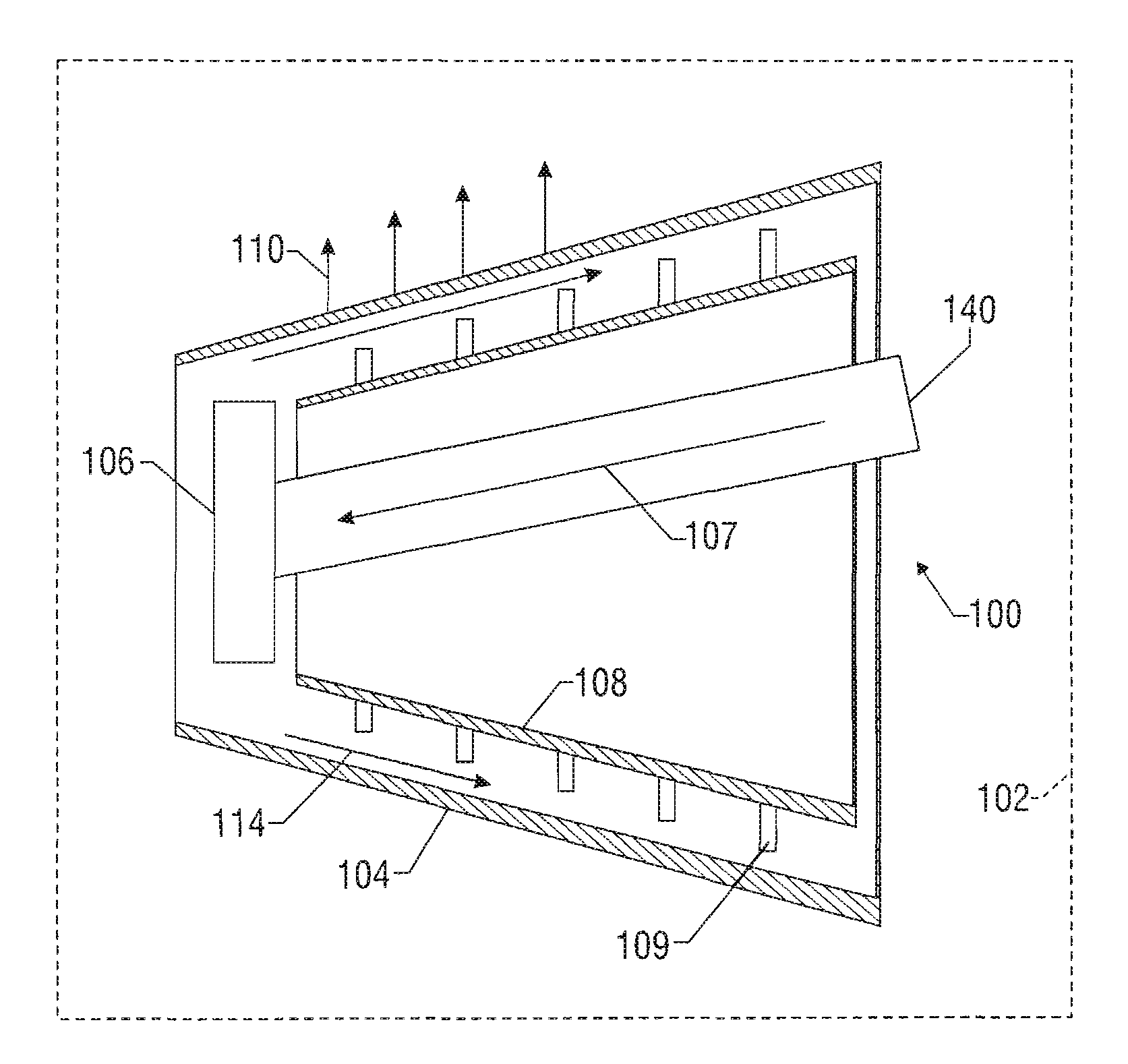
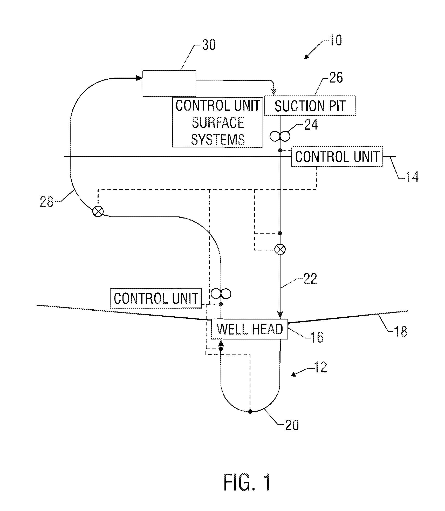
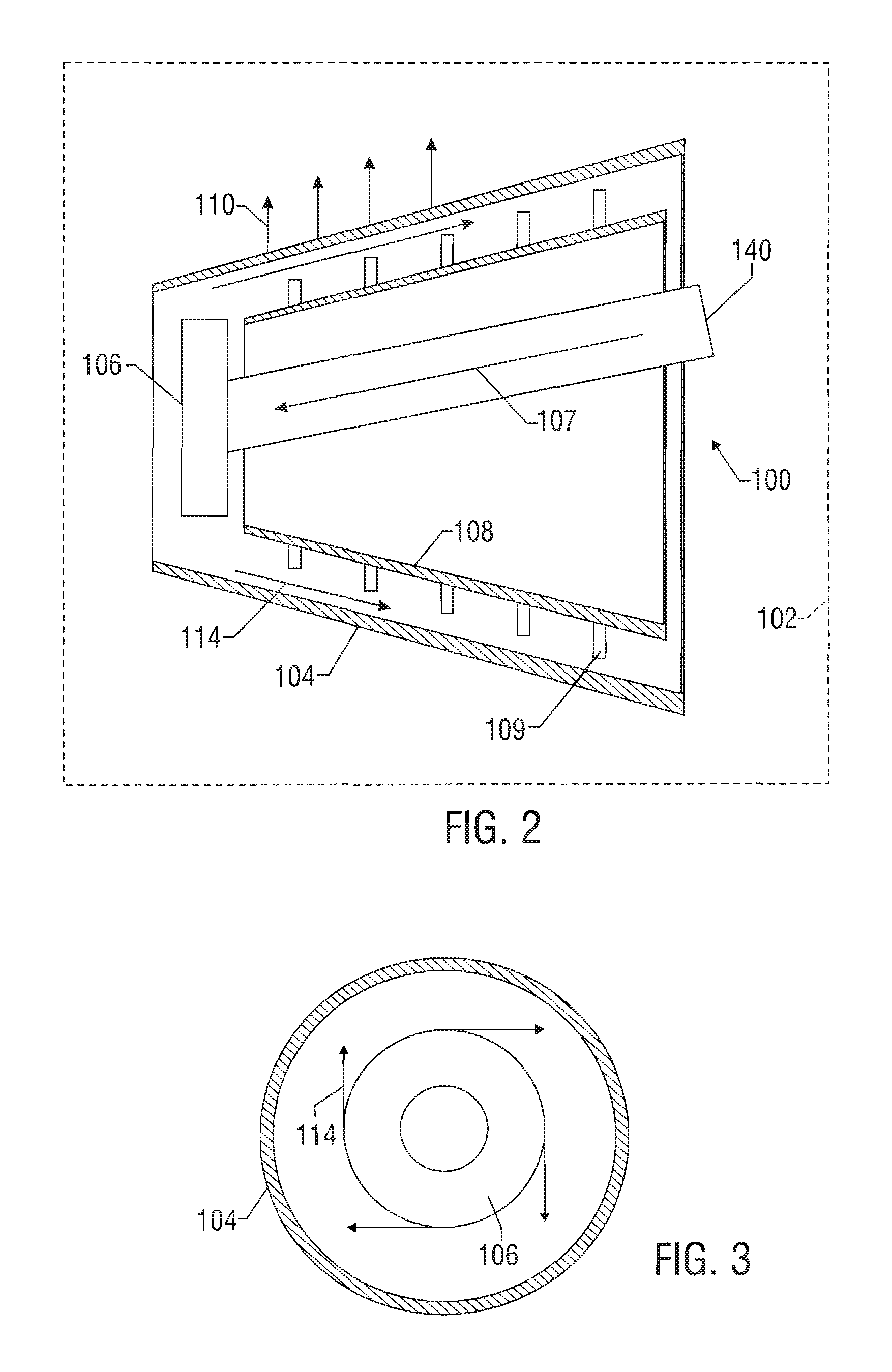
[0020]The present invention relates to devices and methods for processing return fluid recovered from the wellbore during drilling. The return fluid can be received directly from the wellbore or received after some form of initial treatment. Return fluid received directly from the wellbore could have a substantially liquid component with entrained drill cuttings. A treated or pre-processed return fluid can, in actuality, be a slurry having a substantial solids component and some liquids. For simplicity, the term “return fluid” as used herein generally refers to either treated or untreated fluid recovered from the wellbore during drilling. The present invention is susceptible to embodiments of different forms. There are shown in the drawings, and herein will be described in detail, specific embodiments of the present invention with the understanding that the present disclosure is to be considered an exemplification of the principles of the invention, and is not intended to limit the ...


PUM

PropertyMeasurementUnit
centrifugal forceaaaaaaaaaa
tangential velocityaaaaaaaaaa
rotational speedaaaaaaaaaa

Abstract

A cuttings processing system processes return fluid recovered while drilling a wellbore at an offshore location. The processing system includes a separator having an inlet receiving the return fluid, an accelerator coupled to the inlet that accelerates the return fluid, and a conical spinning member that receives the accelerated return fluid from the accelerator and applies a centrifugal force to the return fluid. The acceleration provides the return fluid with a tangential velocity that substantially matches the rotational speed of the conical spinning member. The separator also has a liquid discharge port that discharging the substantially liquid component to a tank or pipe and a solids discharge opening that discharges the substantially solid component out of the separator. In one embodiment, a conveyance device transports the solids component from the separator to a selected location on the offshore facility.

Description

CROSS-REFERENCE TO RELATED APPLICATIONS[0001]NoneBACKGROUND OF THE INVENTION[0002]1. Field of the Invention[0003]The present invention relates to systems for processing return fluid and entrained cuttings.[0004]2. Description of the Related Art[0005]Hydrocarbons such as oil and gas are recovered from a subterranean formation using a wellbore drilled into the formation. When an oil well is drilled, a drilling fluid, commonly referred to as drilling mud, is used to lubricate and cool the drill bit and to carry away cuttings of rock and earth. Commonly, the drilling mud includes water as well as oil, an oil-based carrier, or a diesel-based fluid.[0006]Oily drill cuttings often cannot be discharged directly into the environment due to their adverse effect upon the environment and, therefore, must be processed for disposal in costly disposal wells. Additionally, because of the great value of the residual oil and chemicals contained in them, it has been a common practice to treat the oil ...

Claims


Application Information

Patent Timeline
Patent Type & Authority Patents(United States)
IPC IPC(8): E21B29/12E21B21/00
CPCE21B21/065B01D33/067B04B7/16E21B21/00
Inventor HOLLIER, CHAD
Owner BAKER HUGHES INC
Why Eureka
Try Eureka