Compact compressor

a compressor and compact technology, applied in the direction of piston pumps, positive displacement liquid engines, pump components, etc., can solve the problems of reducing the life of the seals used to create, and achieve the effects of less mass, greater surface area, and less sealing

Inactive Publication Date: 2009-02-17
CAIRE
View PDF8 Cites 17 Cited by
  • Summary
  • Abstract
  • Description
  • Claims
  • Application Information

AI Technical Summary

Benefits of technology

[0004]The invention comprises, in one form thereof, a compact compressor having the intake and output valves incorporated into the piston head. This configuration is compact and also allows the full surface of the compression cylinder to be used for heat dissipation. The simplified cylinder has less mass, greater surface area, and metal to metal contact with the housing for greater dissipation of heat generated by the compressor thereby prolonging the life of the compressor.

Problems solved by technology

Unless sufficiently dissipated, the heat generated by the compressor will reduce the life of the seals used to create a seal between the piston head and the cylinder.
However, because larger piston heads tend to create excessive vibration and noise, a compact compressor having increased heat dissipation is desired in the art.

Method used


Image

  • Compact compressor
  • Compact compressor
  • Compact compressor

Examples


first embodiment

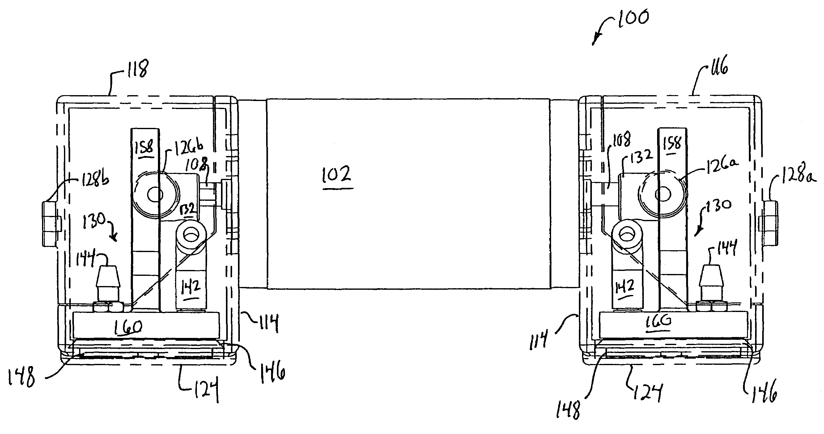
[0040]In the first embodiment, the dual head compact compressor is configured such that both compressor heads output pressurized gas to the supply side of a gas handling system in an alternating manner. More particularly, while one compressor head is in its compression stroke, and thus is supplying pressurized gas to the gas supply, the opposite compressor head is in its draw stroke. In an alternate configuration of a dual head compressor, one compressor head may be configured to supply compressed gas to the supply side of a gas handling system while the second compressor is configured to act as a vacuum drawing gas from the output side of the gas handling system or in an intermediate point within the gas handling system. In a further alternate configuration, the dual head compact compressor includes a single, elongated drive shaft and two or more compressor heads are driven by that shaft. In an even further alternate configuration, larger intake and output flappers such as a disk o...

second embodiment

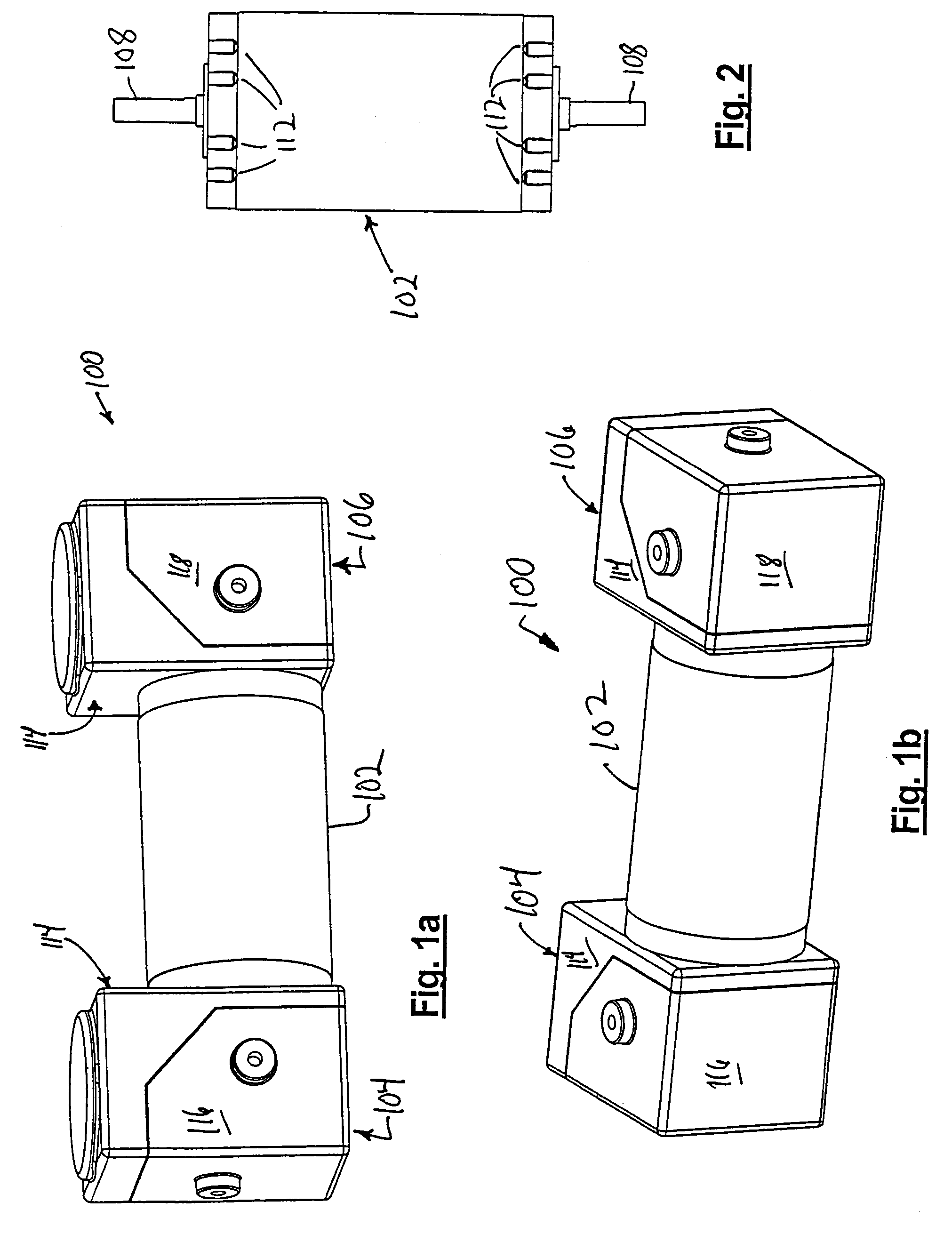
[0041]The compact compressor 300 of a second embodiment is shown in FIG. 15a and includes a single-shaft motor 302, a central housing 316, a pressure-side compressor head 304, and a vacuum-side compressor head 306.

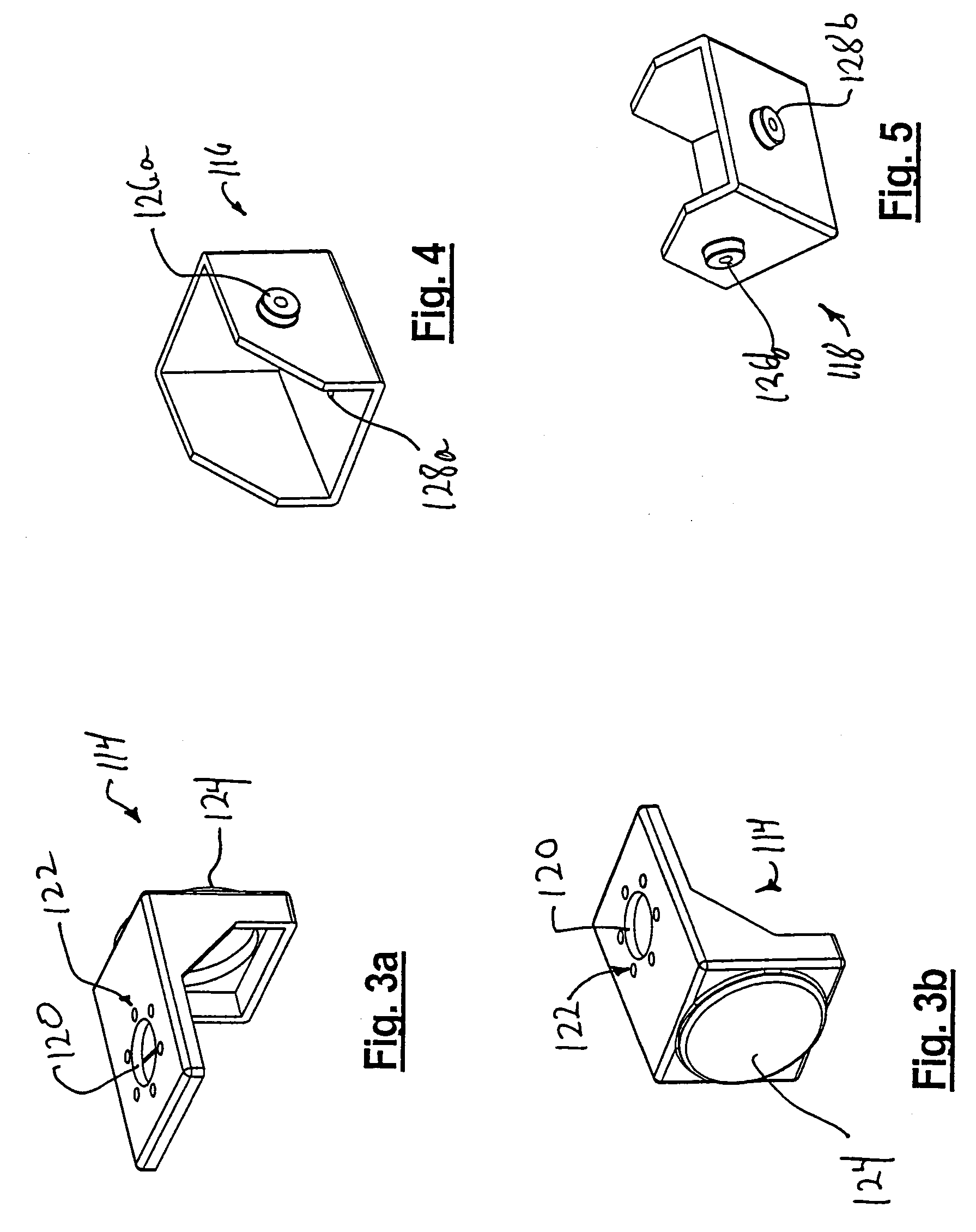
[0042]The motor 302 is a standard electric motor with a single drive shaft 308, shown in FIG. 15b, and is securely mounted to the central housing 316 with the drive shaft 308 penetrating the central housing 316. The central housing 316 is configured to support both compressor heads 304, 306 and includes an inlet chamber 326 with inlet filters 327, an outlet chamber 328 with outlet filters 329, a counterweight 309, a drive shaft support plate 314, and a drive shaft support bearing 315. Depending on the function and the gases to be moved, one of the compressor heads 304, 306 may have a longer stroke and therefore have a larger eccentric core. Also, the peaks of the eccentric cores need not necessarily be 180° from one another. The counterweight 309 is configured to even out ...


PUM


Abstract

A compact compressor including one or more heads. Each of the compressor heads is configured with at least one of the intake and output valves incorporated into the piston head. The compact compressor also has a cylinder with a reduced mass, increased surface area, and metal to metal contact with the housing for greater dissipation of heat generated by the compressor.

Description

CROSS-REFERENCE TO RELATED APPLICATIONS[0001]This application claims priority from Provisional Patent Application Ser. No. 60 / 499,500, filed Sep. 2, 2003.FIELD OF THE INVENTION[0002]This invention relates to gas compressors, especially those used in compact, portable oxygen concentrators.BACKGROUND OF THE INVENTION[0003]Conventional gas compressors have valves incorporated into one end of a compression cylinder. The mass of the valve block impedes transfer of heat generated by the compressor, and rubber seals between the valve block and the cylinder further prevent heat dissipation in the compressor. Unless sufficiently dissipated, the heat generated by the compressor will reduce the life of the seals used to create a seal between the piston head and the cylinder. Conventionally, heat dissipation is achieved by increasing the size of the piston head. However, because larger piston heads tend to create excessive vibration and noise, a compact compressor having increased heat dissipat...

Claims


Application Information

Patent Timeline
Patent Type & Authority Patents(United States)
IPC IPC(8): F04B39/00F04B39/10F04B53/12F04B35/04
CPCF04B35/04F04B39/0016F04B39/1073
Inventor MCCOMBS, NORMAN R.CASEY, ROBERT E.BOSINSKI, ROBERT
Owner CAIRE
Why Eureka
Try Eureka