
Passive broadband long wave and mid-wave infrared optical limiter device

a technology of infrared limiter and long-wave infrared, which is applied in the field of passive infrared (ir) optical limiter device, can solve the problems of high threshold for optical limiter behavior to switch, nonlinear optical absorption process, and relatively narrowband device that is not suitable for handling a broadband range of wavelengths

Inactive Publication Date: 2009-02-24
LOCKHEED MARTIN CORP
View PDF13 Cites 9 Cited by
  • Summary
  • Abstract
  • Description
  • Claims
  • Application Information

AI Technical Summary

Benefits of technology

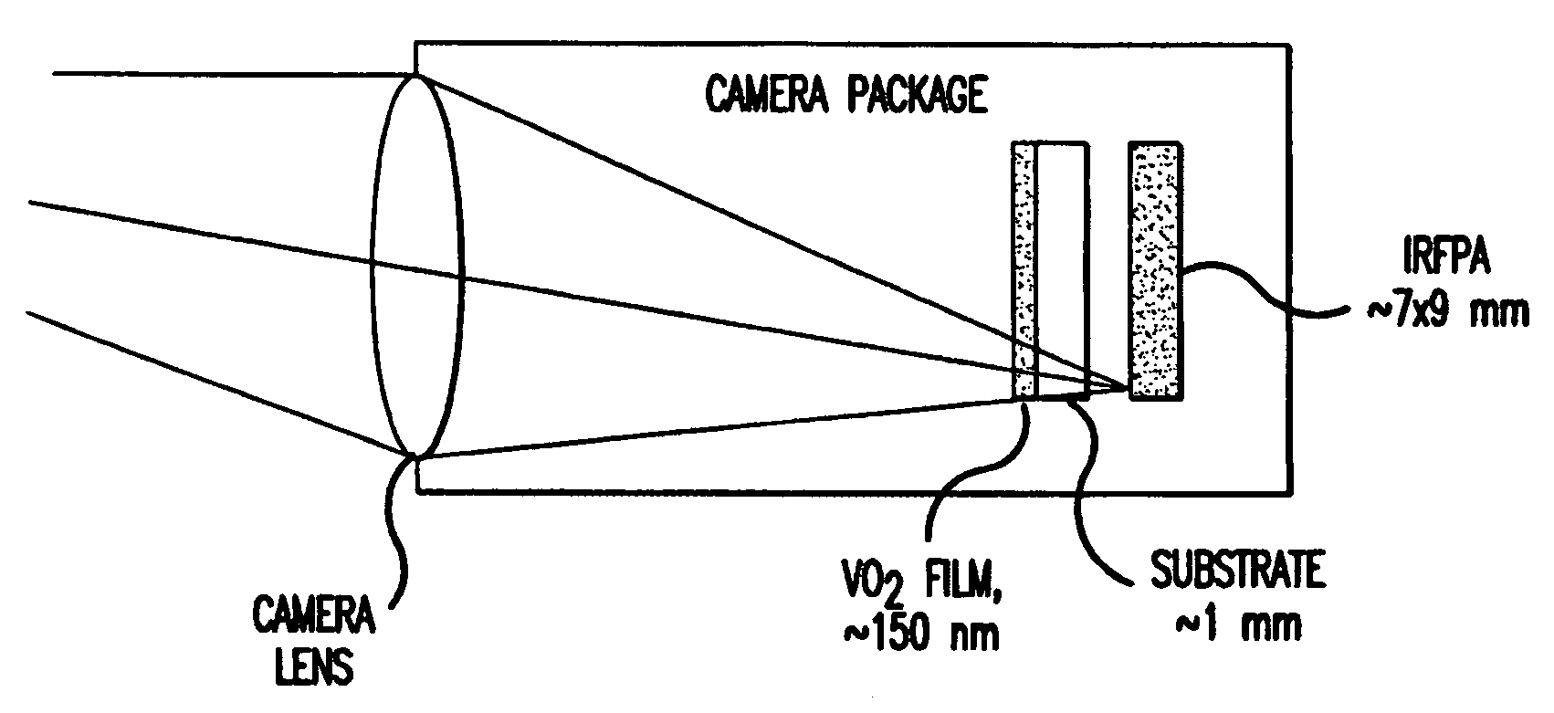
[0009]In one embodiment, the present invention provides a passive broadband long wave infrared radiation (LWIR) optical limiter device made with an IR limiting layer pair selected so that energy from visible and near infrared radiation activates the LWIR optical limiter. The present invention also contemplates a camera protected against sunlight by the incorporation into the camera of a passive broadband LWIR optical limiter device as described herein. The IR limiting layer pair of this invention preferably includes an external layer closer to the source of radiation comprises a material—for example, vanadium dioxide, vanadium sesquioxide, or germanium crystal—that can change quickly from a semiconductor phase to a metal phase upon heating and an internal layer further from the source of radiation comprises material—for example, chalcogenide glass, germanium crystal, or sodium chloride crystal—that strongly absorbs radiation except for radiation of the wavelength region to which the detector is sensitive.
[0010]This invention also provides a method for limiting the amount of radiation impinging on a radiation-sensitive detector device that is responsive to signals of interest having infrared wavelengths of approximately 3 to 14 microns. Such a radiation-sensitive detector device may be, for instance, an infrared camera. This method includes: directing radiation toward the radiation-sensitive detector device, for instance by exposing it to a source of infrared radiation and to ambient sunlight; permitting the radiation to impinge upon, for instance, an infrared focal plane array within the radiation-sensitive detector device when the radiation is below a predetermined threshold (e.g., when the heat generated by the infrared radiation and the ambient sunlight is no greater than 1 W / cm2); and utilizing radiation having wavelengths different from the signals of interest to initiate limiting of the radiation impinging upon the radiation-sensitive detector device when the predetermined threshold is exceeded. More specifically, this last step may, for instance, utilize heat generated by the radiation having wavelengths different from the signals of interest to change the state of a material in the path of the infrared radiation from a semiconductor phase to a metal phase, thereby preventing impingement of the infrared radiation on the infrared focal plane array in the camera.

Problems solved by technology

A disadvantage of such materials arises from their use of nonlinear optical absorption processes.
This leads to a high threshold for the optical limiting behavior to switch on.
It is therefore a relatively narrowband device that is not suitable for handling a broadband range of wavelengths.
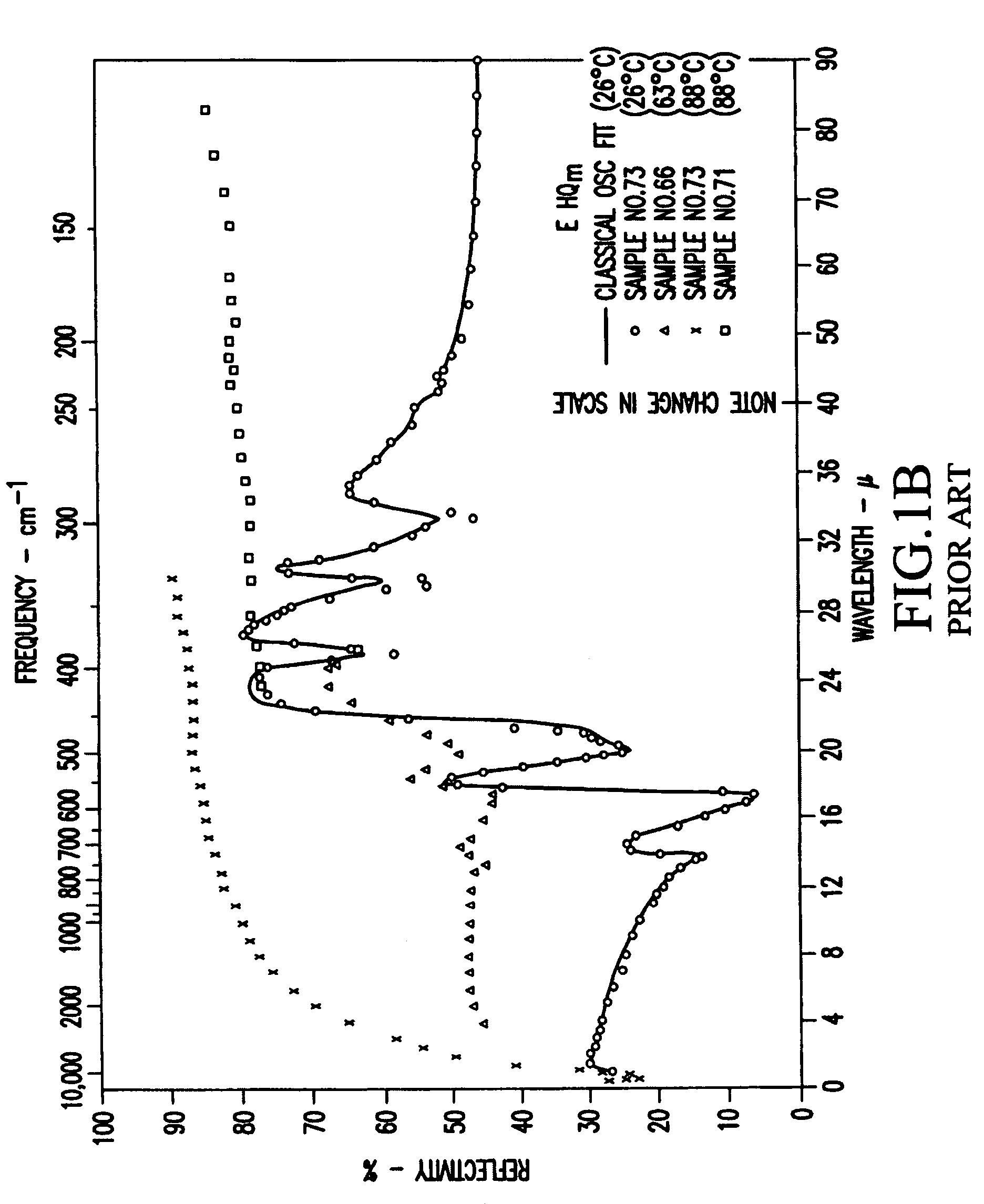
However, they illustrate the monotonic rise expected of free carrier reflection.
Because of its high temperature and brightness, continuous wave radiation can be more harmful to a detector such as a camera than a pulsed narrow bandwidth laser would be.

Method used


Image

  • Passive broadband long wave and mid-wave infrared optical limiter device
  • Passive broadband long wave and mid-wave infrared optical limiter device
  • Passive broadband long wave and mid-wave infrared optical limiter device

Examples


Embodiment Construction

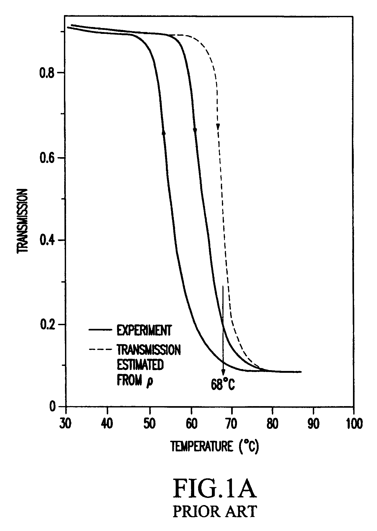
[0017]This invention provides a passive IR optical limiter device for long wave infrared radiation (LWIR) detector protection. The LWIR optical limiter of the present invention makes use of a phase change in a VO2 film at around 68° C., at which temperature the VO2 changes from a semiconductor phase to a metal phase. While the semiconductor phase is essentially transparent, the metal phase is essentially opaque. A material—which strongly absorbs all optical radiation except in the wavelength region that the detector is interested in—is provided as a thin substrate layer attached to the VO2 thin film. When the intensity of the incident light illumination is over a certain threshold, the temperature of the VO2 film increases to over the 68° C. phase change temperature, and the VO2 film changes from “transparent” to “dark”.

[0018]Since the attached layer or substrate absorbs radiation, the LWIR optical limiter of this invention is designed for relatively low peak power, continuous wave,...


PUM

PropertyMeasurementUnit
wavelengthsaaaaaaaaaa
thicknessaaaaaaaaaa

Abstract

Method for limiting amount of radiation impinging on a radiation-sensitive detector device by directing radiation toward the detector, permitting the radiation to impinge upon the detector device when the radiation is below a predetermined threshold, and utilizing radiation having wavelengths different from signals of interest to initiate limiting of the radiation impinging upon the detector when the predetermined threshold is exceeded. The optical limiter includes an IR limiting layer pair selected so that energy from visible and near infrared radiation activates the optical limiter. The limiting layer pair may includes a layer closer to the source of radiation of e.g. vanadium dioxide, vanadium sesquioxide, or germanium crystal and a layer further from the source of radiation of e.g. chalcogenide glass, germanium crystal, or sodium chloride crystal.

Description

FIELD OF THE INVENTION[0001]This invention provides a passive infrared (IR) optical limiter device for long wave and mid-wave infrared radiation detector protection. With respect to infrared wavelengths, wavelengths of approximately 7 to 14 microns are considered to be in the long wave infrared radiation (LWIR) region and wavelengths of approximately 3 to 5 microns are considered to be in the mid-IR region. This invention provides an optical limiter for detectors in the LWIR region. The optical limiter of this invention can also be used in the mid-IR region. In a preferred embodiment, the optical limiter device of this invention comprises an IR limiting layer pair comprising vanadium oxide and a suitable substrate, for instance germanium or AMTIR or sodium carbonate.BACKGROUND OF THE INVENTION[0002]Optical limiters are used for the protection—for instance of eyes, of photodetectors, or of cameras—against unexpected strong illumination. The present invention provides an optical power...

Claims


Application Information

Patent Timeline
Patent Type & Authority Patents(United States)
IPC IPC(8): G02B27/00G02F1/01
CPCG01J1/04G02B5/208H04N5/33G01J1/0488G01J2001/0276
Inventor WU, PINGFANDALAKOS, GEORGELAWRENCE, BRIANLORRAINE, PETERYENISCH, WILLIAM TAYLOR
Owner LOCKHEED MARTIN CORP
Learn More