
Electroplating apparatus and method for making an electroplating anode assembly

an electroplating anode and electroplating technology, which is applied in the direction of electrical-based machining electrodes, machines/engines, manufacturing tools, etc., can solve the problems of blistered platinum deposits, unusable coating thickness variations, and damage to anode assemblies and turbine airfoils

Active Publication Date: 2009-02-24
GENERAL ELECTRIC CO
View PDF5 Cites 5 Cited by
  • Summary
  • Abstract
  • Description
  • Claims
  • Application Information

AI Technical Summary

Benefits of technology

"The invention is about a method and apparatus for electroplating a workpiece. The apparatus includes an unassembled electroplating anode assembly with two structural anode members that are welded together. The first structural anode member has a positioning slot, while the second structural anode member has a positioning tab that fits into the slot. This design allows for precise positioning and faster fabrication times. The technical effect of this invention is to provide a more efficient and precise method for electroplating a workpiece."

Problems solved by technology

Difficulties in precisely positioning the plate members for welding often result in plate positioning errors which lead to undesirable coating thickness variations, blistered platinum deposits, no platinum deposits due to short circuits, and damage to anode assemblies and turbine airfoils when the cathode and anode racks are brought into position for electroplating.

Method used


Image

  • Electroplating apparatus and method for making an electroplating anode assembly
  • Electroplating apparatus and method for making an electroplating anode assembly
  • Electroplating apparatus and method for making an electroplating anode assembly

Examples


Embodiment Construction

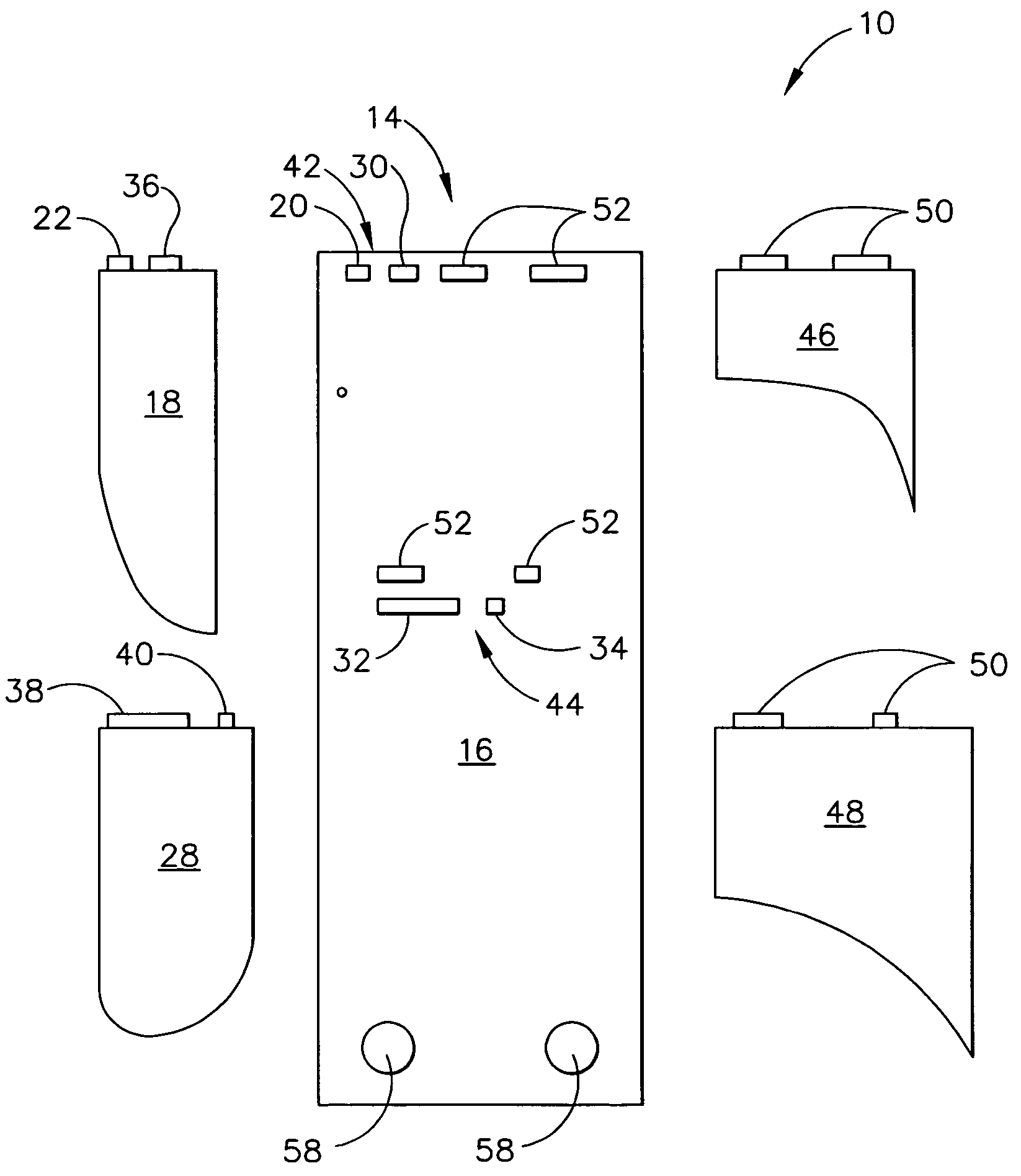
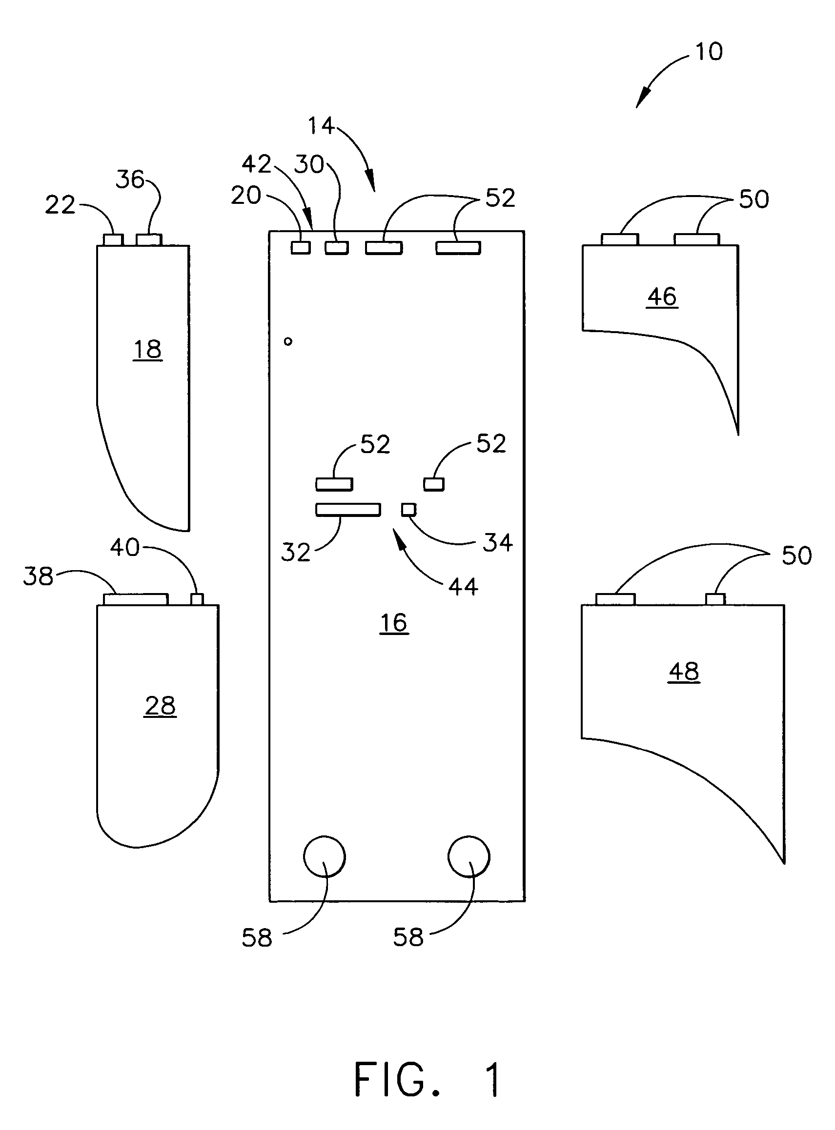
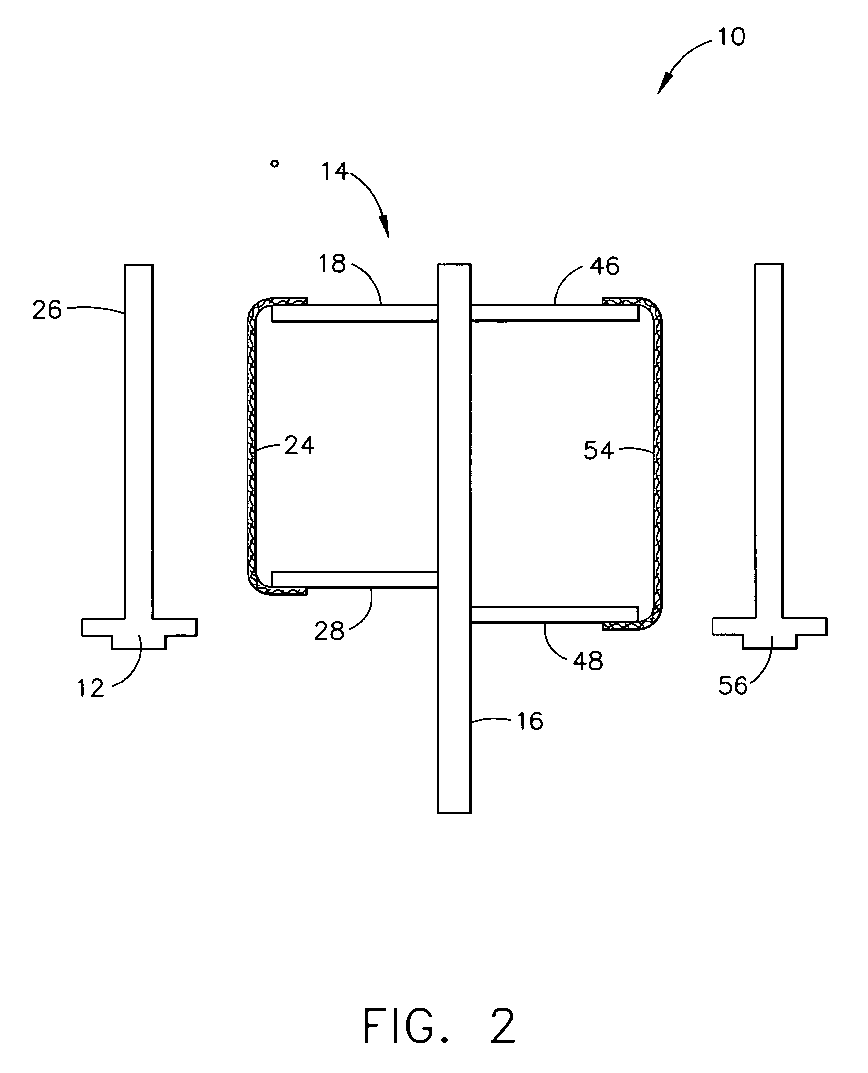
[0011]Referring now to the drawing, FIGS. 1-2 disclose an embodiment of the invention. A first expression of the embodiment of FIGS. 1-2 is an apparatus 10 for electroplating a workpiece 12. The apparatus 10 includes an unassembled electroplating anode assembly 14. The electroplating anode assembly 14 includes weldable first and second structural anode members 16 and 18. By “structural” is meant substantially rigid. The first structural anode member 16 includes a positioning slot 20, and the second structural anode member 18 includes a positioning tab 22 disposable in the positioning slot 20. It is noted that describing the apparatus as having a particular component (such as an electroplating anode assembly) means that the apparatus has at least one particular component (such as at least one electroplating anode assembly). Likewise, describing a component as having a particular feature (such as a positioning slot) means that the component has at least one particular feature (such as...


PUM

PropertyMeasurementUnit
distanceaaaaaaaaaa
lengthaaaaaaaaaa
shapeaaaaaaaaaa

Abstract

Apparatus for electroplating a workpiece includes an unassembled electroplating anode assembly having weldable first and second structural anode members. The first structural anode member includes a positioning slot. The second structural anode member includes a positioning tab disposable in the positioning slot. A method for making an electroplating anode assembly includes obtaining an electroplating-anode-assembly first structural anode member having a positioning slot and obtaining an electroplating-anode-assembly second structural anode member having a positioning tab. The method also includes locating the positioning tab in the positioning slot and welding together the first and second structural anode members.

Description

BACKGROUND OF THE INVENTION[0001]The present invention relates generally to applying a coating on a workpiece, and more particularly to an electroplating apparatus and to a method for making an electroplating anode assembly.[0002]It is known to coat turbine airfoils, such as turbine airfoils of an aircraft engine, with platinum aluminide diffusion coatings for protection against high temperature oxidation and corrosion. To develop the platinum aluminide coating, the parts are first platinum electroplated. It is known to use the electrolyte Pt(NH3)4HPO4 for platinum electroplating turbine airfoils.[0003]In a known electroplating method, a cathode rack supports several turbine airfoils and an anode rack supports several electroplating anode assemblies. The turbine airfoils and the electroplating anode assemblies are in contact with the Pt(NH3)4HPO4 electrolyte, and a rectifier is employed to apply a voltage between the cathode and anode racks for platinum electroplating of the turbine...

Claims


Application Information

Patent Timeline
Patent Type & Authority Patents(United States)
IPC IPC(8): C25B11/02
CPCC25D17/10C25D17/12F01D5/288F05D2230/31F05D2300/143
Inventor ROSENZWEIG, MARK ALANZIMMERMAN, JR., ROBERT GEORGEEVANS, SR., JOHN D.
Owner GENERAL ELECTRIC CO
Learn More