Buck converter with demagnetization detection of the inductor

a technology of demagnetization detection and buck converter, which is applied in the direction of power conversion systems, dc-dc conversion, instruments, etc., to achieve the effect of reducing switching losses

Inactive Publication Date: 2009-02-24
PULS GMBH
View PDF6 Cites 24 Cited by
  • Summary
  • Abstract
  • Description
  • Claims
  • Application Information

AI Technical Summary

Benefits of technology

[0015]In another modification, the diode is embodied in the form of an electronic switch. In particular, in order to replace the diode with a MOSFET, it is possible to reduce the switching losses, particularly during an overload operation of the buck converter.
[0016]In particular, it is possible to replace the electronic switch with at least one (bipolar) transistor, a field effect transistor, a MOSFET, a thyristor, or an IGBT. It is also possible for combinations of the above-mentioned components to be used as one or more electronic switches.

Problems solved by technology

The line impedance generates harmonics that influence the line voltage and can lead to malfunctions.

Method used


Image

  • Buck converter with demagnetization detection of the inductor
  • Buck converter with demagnetization detection of the inductor
  • Buck converter with demagnetization detection of the inductor

Examples


Embodiment Construction

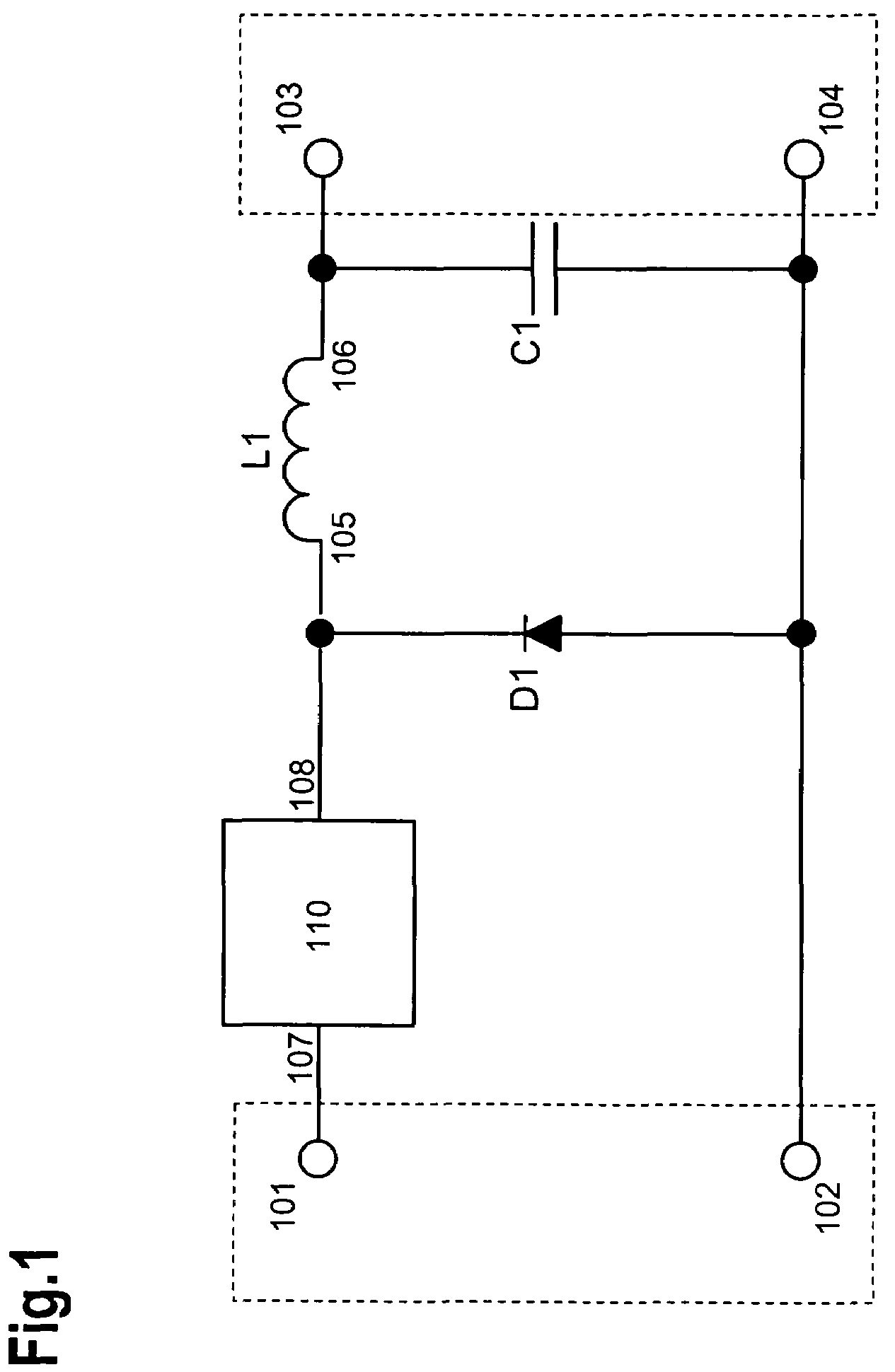
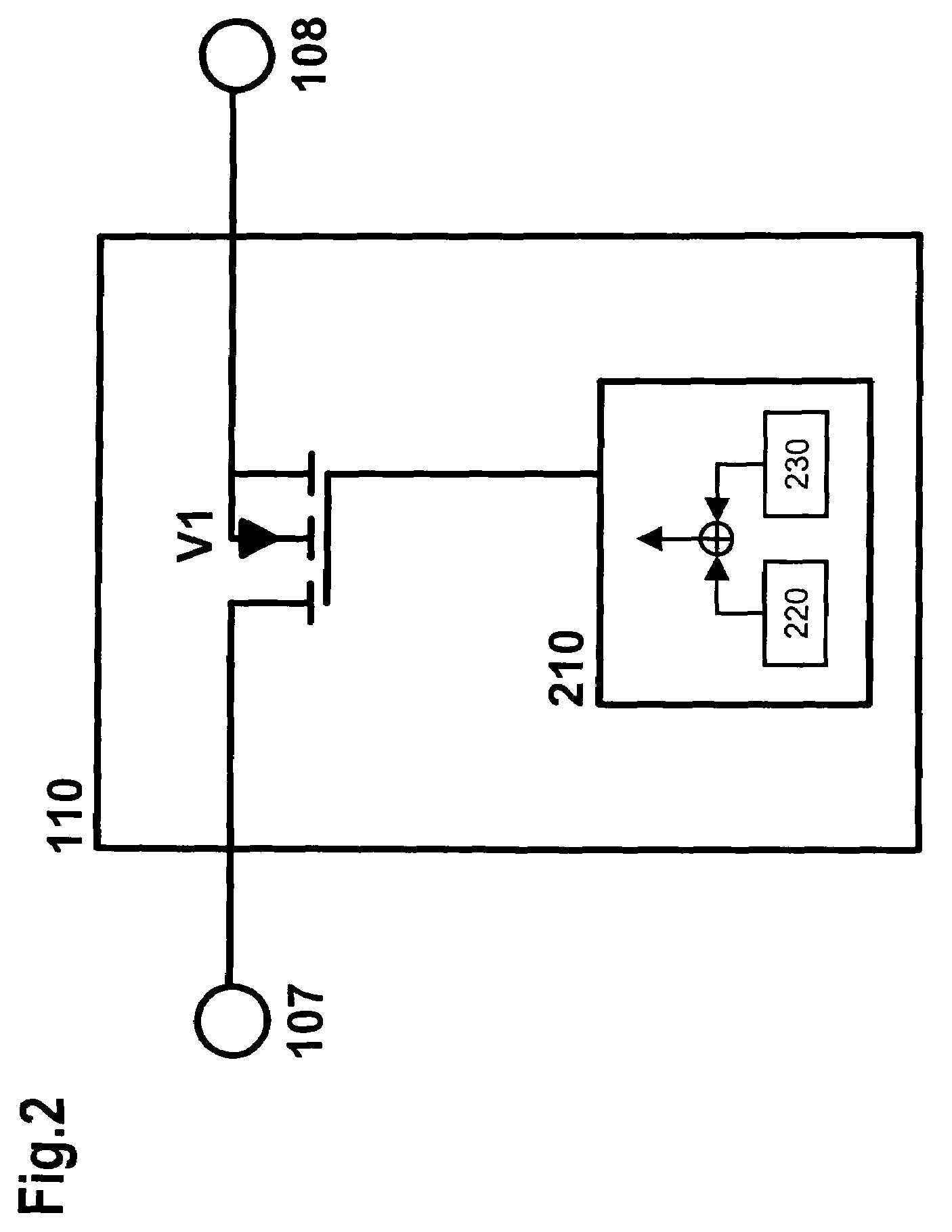
[0045]FIG. 1 shows a circuit diagram of a buck converter that is equipped with an input (with connections 101 and 102), an output (with connections 103 and 104), a diode D1, a switch 110 (with connections 107 and 108), an inductance L1 (with connections 105 and 106), and a capacitor C1.

[0046]The connection 101 of the input is connected to the connection 107 of the switch 110. The connection 108 of the switch 110 is connected to the cathode of the diode D1 and to the connection 105 of the inductance L1. The connection 106 of the inductance L1 is connected to the connection 103 of the output. The capacitor C1 is situated in parallel with the output, i.e. it is connected to the connections 103 and 104. If the capacitor C1 is embodied in the form of an electrolytic capacitor, then its positive pole is connected to the connection 103 of the output. The connection 102 of the input is connected to the connection 104 of the output and to the anode of the diode D1.

[0047]Optionally, the polar...


PUM


Abstract

A buck converter is equipped with a switch, a diode, an inductance, a capacitor, an input with a first connection and second connection, and an output with a first connection and second connection. The first connection of the input is connected to the first connection of the output via a series circuit comprised of the switch and the inductance; in particular, the switch is provided on the input side and the inductance is provided on the output side. In addition, the cathode of the diode is connected to the connection between the switch and the inductance while the anode of the diode is connected to the second connection of the input and to the second connection of the output. The capacitor is connected in parallel with the connections of the output. It is possible to trigger the switch by combining a first signal with a second signal and a third signal corresponding to a control variable from the output of the buck converter may be used to adjust the output signal.

Description

BACKGROUND OF THE INVENTION[0001]1. Field of the Invention[0002]The invention relates to a buck converter, a triggering method, and a use of the buck converter.[0003]2. Description of the Related Art[0004]Power supplies, in particular switching power supplies and switched mode power supplies as well as primarily and secondarily clocked switching controllers are known from [1]. Every electrical power consuming component requires a supply of electrical power, which is provided by a power supply and / or a power pack. Throughout the world, power lines are used as transmission lines in order to supply current and voltage to a virtually limitless array of electrical devices via electrical outlets. To this end, standardized alternating currents, e.g. 120 volts in the USA and 230 volts in Germany, are customarily supplied via the power lines.[0005]In power factor correction, power consuming components in the circuit, in particular capacitances and inductances of a circuit, are compensated fo...

Claims


Application Information

Patent Timeline
Patent Type & Authority Patents(United States)
IPC IPC(8): G05F1/565
CPCH02M3/156
Inventor FRIEDRICH, HEINER
Owner PULS GMBH
Why Eureka
Try Eureka