Eureka AIR delivers breakthrough ideas for toughest innovation challenges, trusted by R&D personnel around the world.

Delay guarantee path setting system

a technology of path setting and delay, applied in the field of delay guarantee path setting system, can solve the problems of low possibility that the request is accepted, low possibility that any request imposing more strict limitations on the delay is accepted thereafter, and the possibility of 3 being longer, so as to reduce the probability of call loss

Inactive Publication Date: 2009-02-24
FUJITSU LTD
View PDF20 Cites 26 Cited by
  • Summary
  • Abstract
  • Description
  • Claims
  • Application Information

AI Technical Summary

Benefits of technology

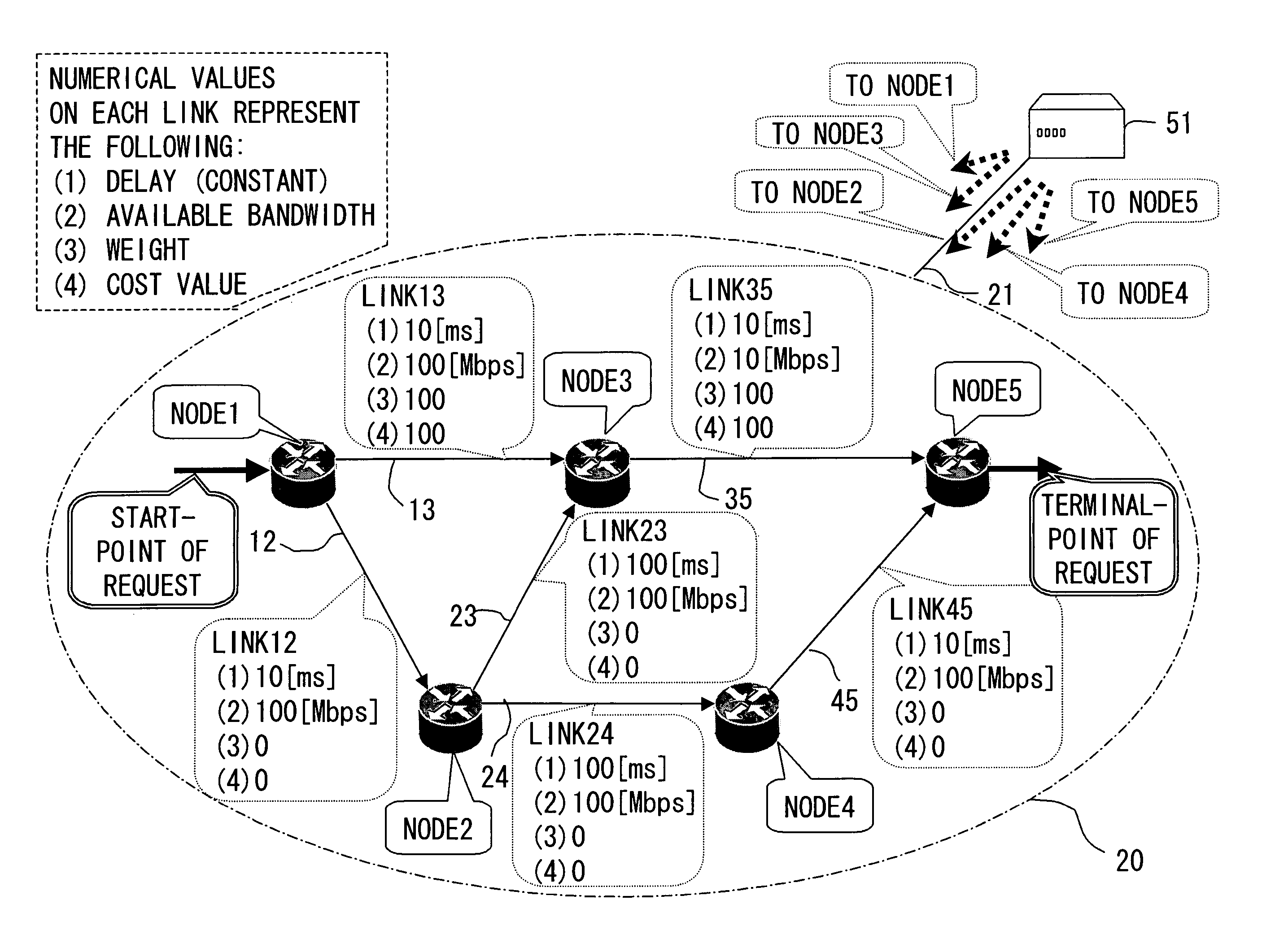
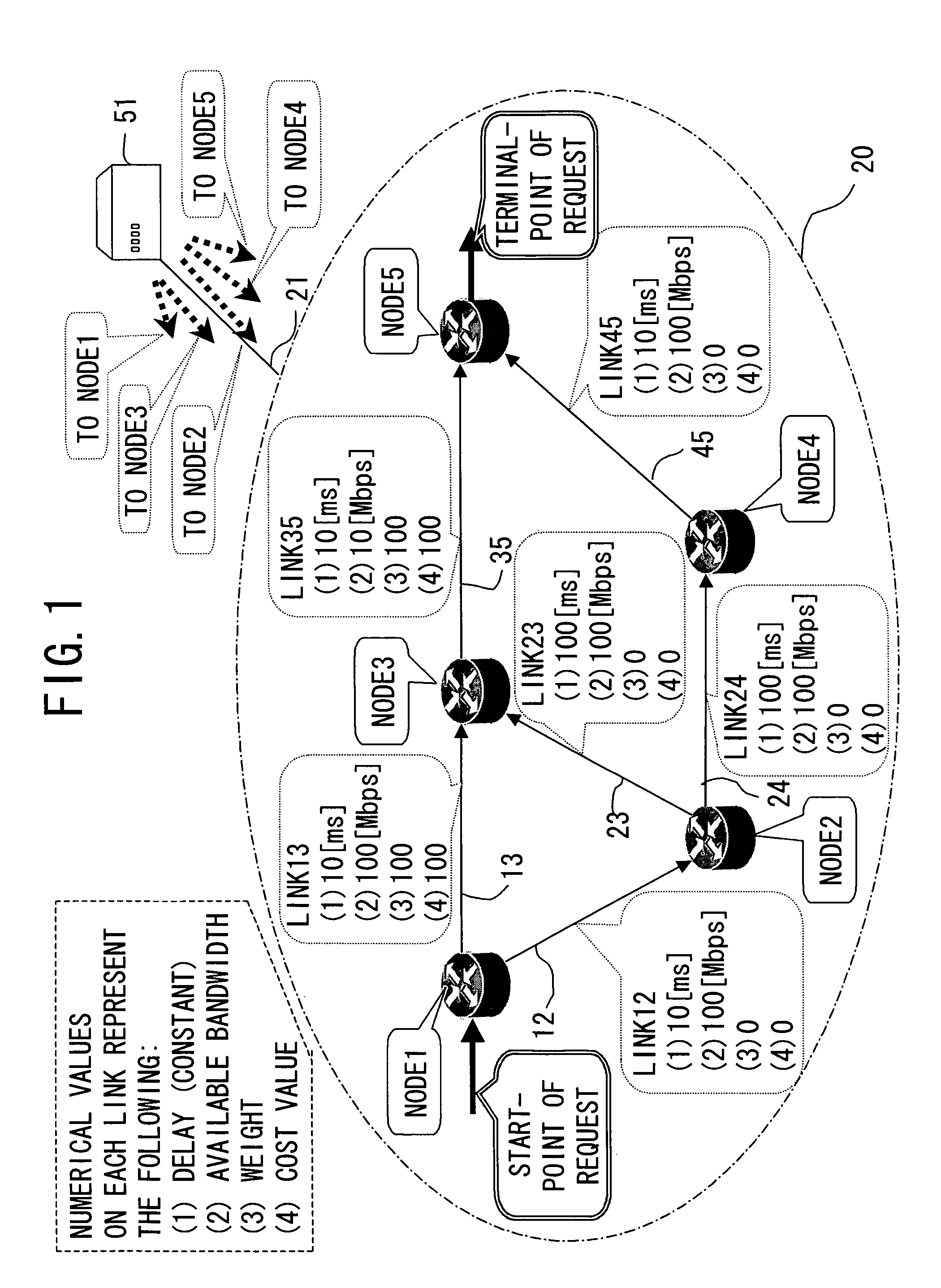
[0053]It is an object of the present invention to improve a usability of network resources in a network that guarantees bandwidth and delay. More specifically, it is an object of the present invention to provide a delay guarantee path setting system that enables reduction in call loss probability and acceptance of more delay guarantee path setting requests in the network.
[0058]Therefore, according to the present invention, it is possible to select / set the traffic transfer path according to an ability to meet a prospective delay request. This allows, in turn, more delay guarantee messages to be accepted while making efficient use of network resources and reducing a call loss probability.
[0066]Therefore, the links having smaller available bandwidth are less likely to be selected, whereby it is possible to make efficient use of the network resources.
[0068]According to the present invention, a system is realized, which enables reduction in call loss probability and acceptance of more delay guarantee path setting requests.

Problems solved by technology

However, the total delay time of the path 3 is longer than the requested delay time of 50 ms (S904 of FIG. 9; NO), and does not comply with the requested delay.
However, the total delay time of the path 3 is longer than the requested delay time, 50 ms (S913 of FIG. 12; NO), and thus does not comply with the requested delay time, so the request is judged unacceptable (S914 of FIG. 12).
If some link leaves no available bandwidth, which narrows the list of candidate paths to be selected, resulting in a low possibility that the request is accepted.
As a result, the bandwidth of the minimum delay path is used, resulting in a low possibility that any request that imposes more strict limitations on the delay is accepted thereafter.
However, an available bandwidth in each link is out of consideration, so a link insufficient in free bandwidth may be selected, leading to nonuniform use amounts of bandwidth.
As a result, a call loss (in case that the request is not accepted because of failing in detection of a path that meets requests) increases.
In this way, in searching and setting a path that guarantees bandwidth and delay, the conventional art for selecting the minimum delay path or delay limitation minimum hop path is inefficient in usability of network resources, and suffers from a problem in that a larger number of delay guarantee path setting requests cannot be accepted.

Method used


Image

  • Delay guarantee path setting system
  • Delay guarantee path setting system
  • Delay guarantee path setting system

Examples


applied example

[0154]In this example, the system is applied to another network configuration (model), and simulation is carried out. The simulation results are explained with reference to FIGS. 6 and 7. This simulation includes one in the case where the conventional system is applied to the same network model as well, and effects are compared against those of the present invention.

[0155]FIG. 6 shows a network configuration used in the simulation. Fifteen nodes are connected to one another to constitute the network. The bandwidth of each link 30 denoted by the thick line out of the links connecting between the nodes is 2.4 Gbps, the bandwidth of the rest is 600 Mbps.

[0156]Prior to the simulation, values related to the path set processing are set as follows.

[0157]A delay time for each link is selected and set from a range of 1 to 50 ms at random.

[0158]Also, the start-point node in each delay guarantee path setting request is randomly selected from the nodes 1, 4, and 5 (denoted by S in the figure), ...

modified example

[0163]In the embodiment of the present invention, the network management control device (NMS 51) is connected to the objective network through a given management network to thereby manage the information about the respective nodes and links constituting the network, and perform path setting in receiving the delay guarantee path setting request. This function may be imparted to each node that may serve as start-point node / terminal-point node out of the nodes constituting the network. Also, all the nodes that constitute the network can serve as the start-point node / terminal-point node. Besides, the nodes that can serve as the start-point node / terminal-point node may be communication apparatuses such as routers and so on.

[0164]Also, in the embodiment of the present invention, in response to the delay guarantee path setting request, all paths that comply with the requested bandwidth and requested delay are detected, and the total cost values are calculated for every path. However, anoth...


PUM


Abstract

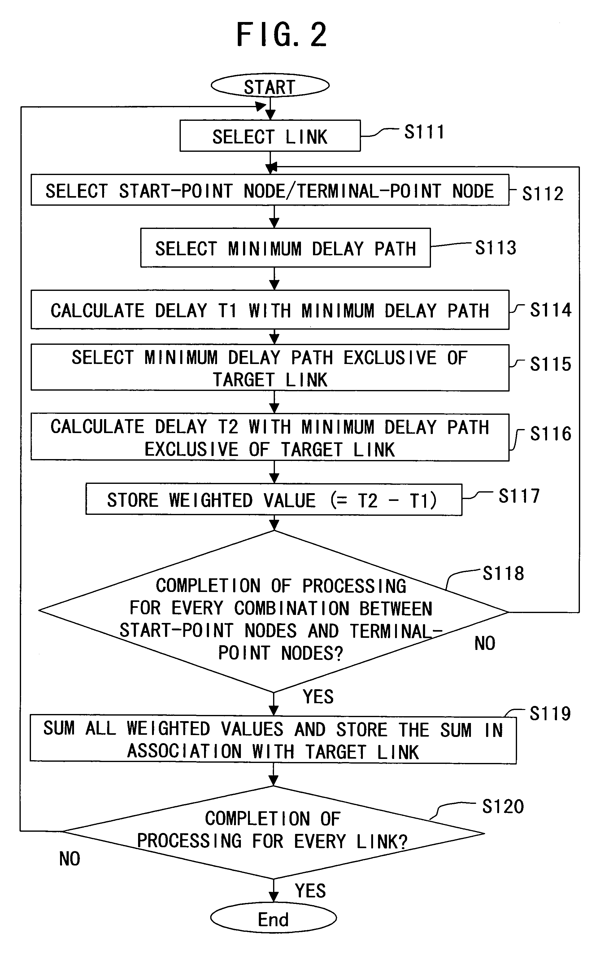
A delay guarantee path setting system, which sets a traffic transfer path in a network, based on a delay guarantee message that requests path setting that guarantees a bandwidth and a delay, and in the system, the network management node defines a weighted value for each link connecting between the nodes according to an ability to comply with a requested bandwidth and a requested delay in the delay guarantee message, and selects, upon receiving the delay guarantee message, a path that complies with requests in the received delay guarantee message, and has the weighted value of a link in the path which meets a predetermined condition.

Description

BACKGROUND OF THE INVENTION[0001]1. Field of the present invention[0002]The present invention relates to a delay guarantee path setting system for traffic transfer.[0003]2. Description of the Related Art[0004]Upon traffic transfer in a network, in order to guarantee Qos (quality of service) concerning a bandwidth or delay, it is necessary to search for such a route that meets a Qos request and set the obtained route as a path by referring configuration information or resources information of the network.[0005]More specifically, a router in the network or network management control device has a database storing the configuration information or resources information of the network and searches the database for such a path that meets the QoS request in a given segment requested by a user. The path selected from among this search undergoes paths setting with an explicit route using a signaling protocol, for example, RSVP-TE (Resource reSerVation Protocol Traffic Engineering extension) f...

Claims


Application Information

Patent Timeline
Patent Type & Authority Patents(United States)
IPC IPC(8): H04L12/28H04L45/121
CPCH04J3/0682H04L41/0663H04L41/0896H04L41/5009H04L43/0811H04L43/0852H04L45/12H04L45/121H04L45/123H04L41/0826H04L43/0829
Inventor YAMADA, HITOSHIOKAMURA, AKIKO
Owner FUJITSU LTD
Why Eureka
Eureka Blog
Learn More