
Method of monitoring and/or determining the condition of a force-measuring device, and force-measuring device

a technology of force-measuring cell and force-measuring device, which is applied in the direction of instruments, weighing apparatus details, weighing apparatus, etc., can solve the problems of long downtime of system or defective products, increase the relative humidity of the housing interior, and the corrosion of parts of the force-measuring cell or the electronic components of the signal-processing circuitry, etc., to achieve accurate calculation of the remaining operating life

Active Publication Date: 2009-03-03
METTLER TOLEDO GMBH
View PDF32 Cites 352 Cited by
  • Summary
  • Abstract
  • Description
  • Claims
  • Application Information

AI Technical Summary

Benefits of technology

[0014]A continuous determination of the sensor signals has the advantage that the entire time profile of the sensor signal is available which provides information about the magnitude and duration of the exposure of the force-measuring cell to the respective parameter of the atmospheric climate of the interior space, which allows the time profile to be used for the calculation of the remaining operating lifetime.
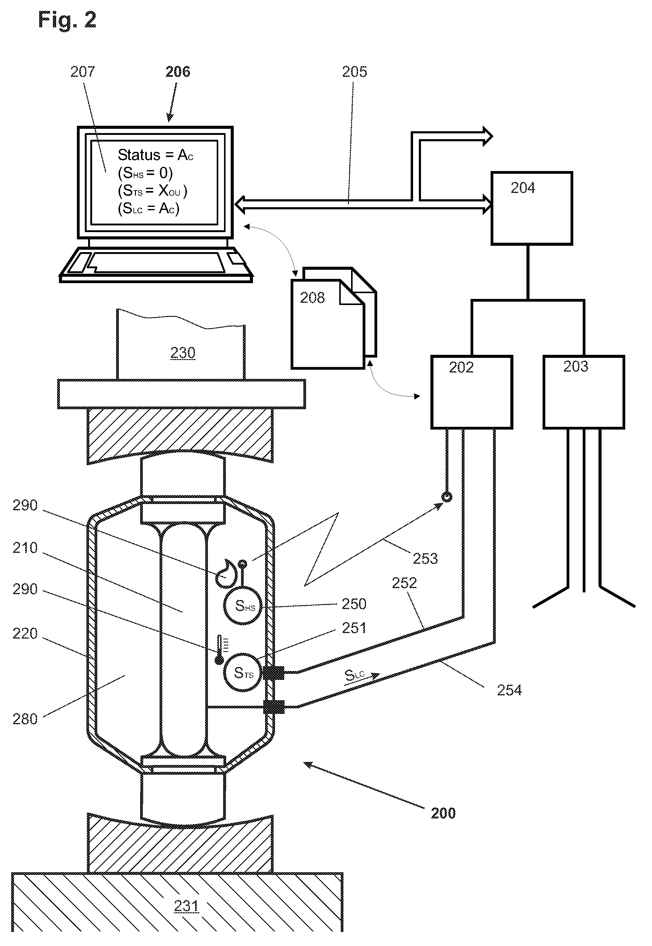
[0023]All sensors can be active systems which detect a change automatically and send a sensor signal to the computing unit and / or the data output device. But passive sensors, too, can be used which are periodically interrogated by the computing unit to obtain the sensor signals. The data acquired in this manner already allow a coarse calculation of the remaining operating lifetime in that for every violation of a threshold value or maximum value a set amount is subtracted from the predefined operating lifetime. With a continuous determination of the sensor signals which is analogous to a time profile of the signals it is possible, due to the simultaneously measured lengths of the time segments, to make a very accurate calculation of the remaining operating lifetime.

Problems solved by technology

If the measuring device is built into an industrial installation with a high degree of automation, a defect in the measuring device can often lead to a long downtime of the system or to defective products.
Still, with an error in manipulation it is possible that for example a liquid penetrates into the interior of the housing and increases the relative humidity of the housing interior to such a degree that parts of the force-measuring cell or the electronic components of the signal-processing circuitry become corroded.
With exposure to unsuitable environments during transportation and storage, it is possible that condensation occurs inside the housing, which can severely compromise the measurement performance.
Depending on the housing enclosure, an inspection of the force-measuring cell is very expensive or even impossible.
A periodic checking of the force-measuring devices used in systems installations is complicated and expensive.
While this kind of treatment of the weighing signal can adequately compensate for the effects of the ambient environment on the weighing result, it cannot provide a determination of the actual condition of the force-measuring cell.

Method used


Image

  • Method of monitoring and/or determining the condition of a force-measuring device, and force-measuring device
  • Method of monitoring and/or determining the condition of a force-measuring device, and force-measuring device
  • Method of monitoring and/or determining the condition of a force-measuring device, and force-measuring device

Examples


Embodiment Construction

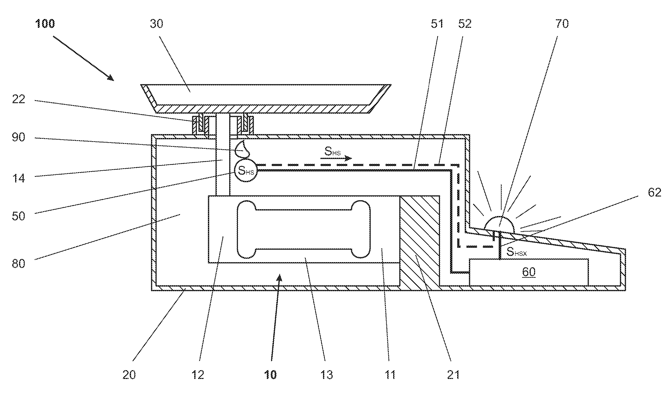
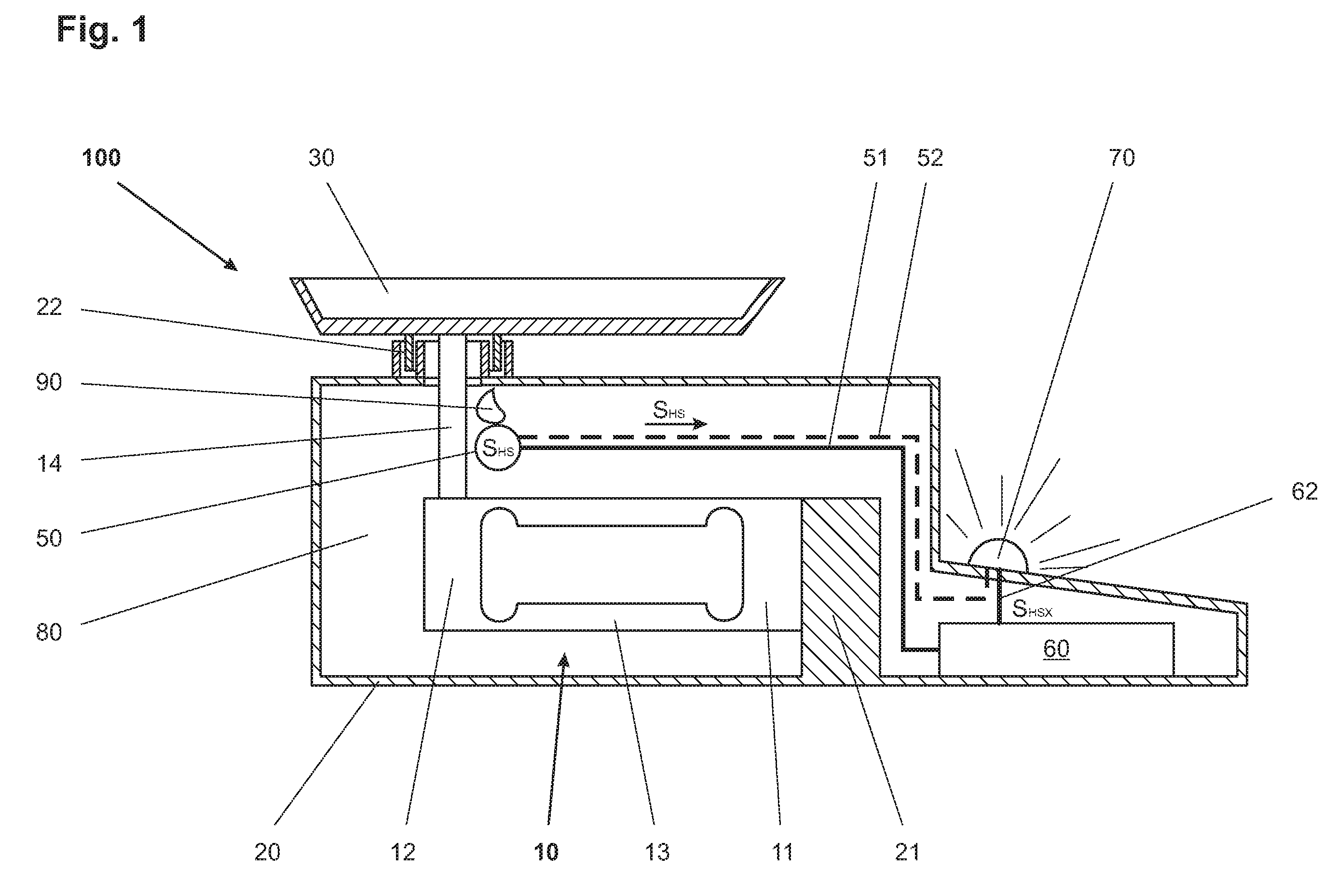
[0060]FIG. 1 gives a schematic representation of a force-measuring device, specifically a balance, shown in a sectional view. A force-measuring cell 10 has a stationary part 11 and a load-receiving part 12 which are connected to each other through an intermediate part 13. The force-measuring cell 10, which is arranged in the interior space 80 of a housing 20, is rigidly connected by its stationary part 11, through the stationary support 21, to the housing 20. A load-receiver 30 in the form of a weighing pan which is arranged outside of the housing 20 is connected by way of a force-transmitting rod 14 to the load-receiving part 12 of the force-measuring cell 10 which is arranged in the interior space 80. The force-transmitting rod 14 traverses the housing 20 without touching the latter, extending though a passage opening 22 of the housing 20. The passage opening 22 of the housing is configured in such a way that the penetration of dirt, dust and humidity is avoided as much as possibl...


PUM


Abstract

In a method for monitoring and / or determining the condition of a force-measuring device with at least one housing that has an interior space and with at least one force-measuring cell installed in the interior space of the at least one housing, at least one parameter of the atmospheric climate of the interior space is measured with at least one sensor that is arranged in the interior space of the housing or with at least one sensor that is arranged at the housing, wherein said parameter is of a kind that has an influence on the operating lifetime of the force-measuring cell; and a sensor signal corresponding to the measured parameter of the atmospheric climate of the interior space is transmitted to a computing unit and / or to a data output device.

Description

CROSS-REFERENCE TO RELATED APPLICATIONS[0001]This application claims a right of priority under 35 USC §119 from European patent application 05 110 766.2, filed 15 Nov. 2005, the content of which is incorporated by reference as if fully recited herein.TECHNICAL FIELD[0002]The embodiments disclosed herein relate to a method of monitoring and / or determining the condition of a force-measuring device with at least one housing having an interior space and with at least one force-measuring cell installed in the interior space of the at least one housing, and it also relates to a force-measuring device that is suitable for carrying out the method.BACKGROUND OF THE ART[0003]Many force-measuring devices, in particular gravimetric measuring instruments such as for example balances, thermogravimetric instruments, instruments for the gravimetric determination of moisture content, weighing modules for tank installations and reactor containers, weighing modules and multiple weighing devices in fil...

Claims


Application Information

Patent Timeline
Patent Type & Authority Patents(United States)
IPC IPC(8): G01G23/01
CPCG01G21/30G01G23/3728G01G23/01
Inventor TELLENBACH, JEAN-MAURICEAEPLI, DANIELBAUMEL, HELMUT
Owner METTLER TOLEDO GMBH
Learn More