Composite and metal component production, forming and bonding system

a metal component and composite technology, applied in the direction of ceramic shaping cores, turning machine accessories, drawing profiling tools, etc., can solve the problems of not being able to prepare the next composite lay-up, not being able to readily change the mould to produce a different composite component, and shortcuring times for composite products produced

Inactive Publication Date: 2009-03-03
QUICKSTEP TECH
View PDF20 Cites 43 Cited by
  • Summary
  • Abstract
  • Description
  • Claims
  • Application Information

AI Technical Summary

Benefits of technology

[0013]It is therefore an object of the present invention to provide an improved system and method for producing composite or bonded metal components.

Problems solved by technology

In practice, this results in curing times for the production composite products that are substantially shorter than that possible with conventional autoclave production processes.
Furthermore, in the arrangements where pressure is applied to opposing sides of a lay-up, the pressure can be balanced such that it is unnecessary to use apparatus having high structural strength to support any applied heavy loads.
PCT / AU95 / 00593 is in use, it is not possible to prepare the next composite lay-up until the composite component currently being manufactured has been cured or formed.
Furthermore, it is not possible to readily change moulds to produce a different composite component as this requires the floating rigid or semi rigid mould to be detached from the pressure chamber and to be replaced with another rigid or semi rigid mould of a different configuration.
With the mould fixed in the wall of the pressure chamber it is difficult to maneuver the mould to get access to the mould for example to place the composite materials into the mould.
In addition it is difficult to work on the mould to place the stiffeners into the part whilst it is in the pressure cell with the pressure chambers surrounding it.
However this is not preferable as the composite component is not generally rigid and tends to flex until all stiffeners are in position.
This is difficult to accommodate within the present process without split pressure chambers and sophisticated locking mechanisms in the walls of the mould to hold the moulds together to ensure no loss of fluids.
Also, it is difficult to adapt the pressure chamber to produce composite components of widely different sizes because of the floating mould arrangement.
This is therefore a “batch” process where it is not possible to undertake any further action until the current curing, forming procedure is completed.

Method used


Image

  • Composite and metal component production, forming and bonding system
  • Composite and metal component production, forming and bonding system
  • Composite and metal component production, forming and bonding system

Examples


Embodiment Construction

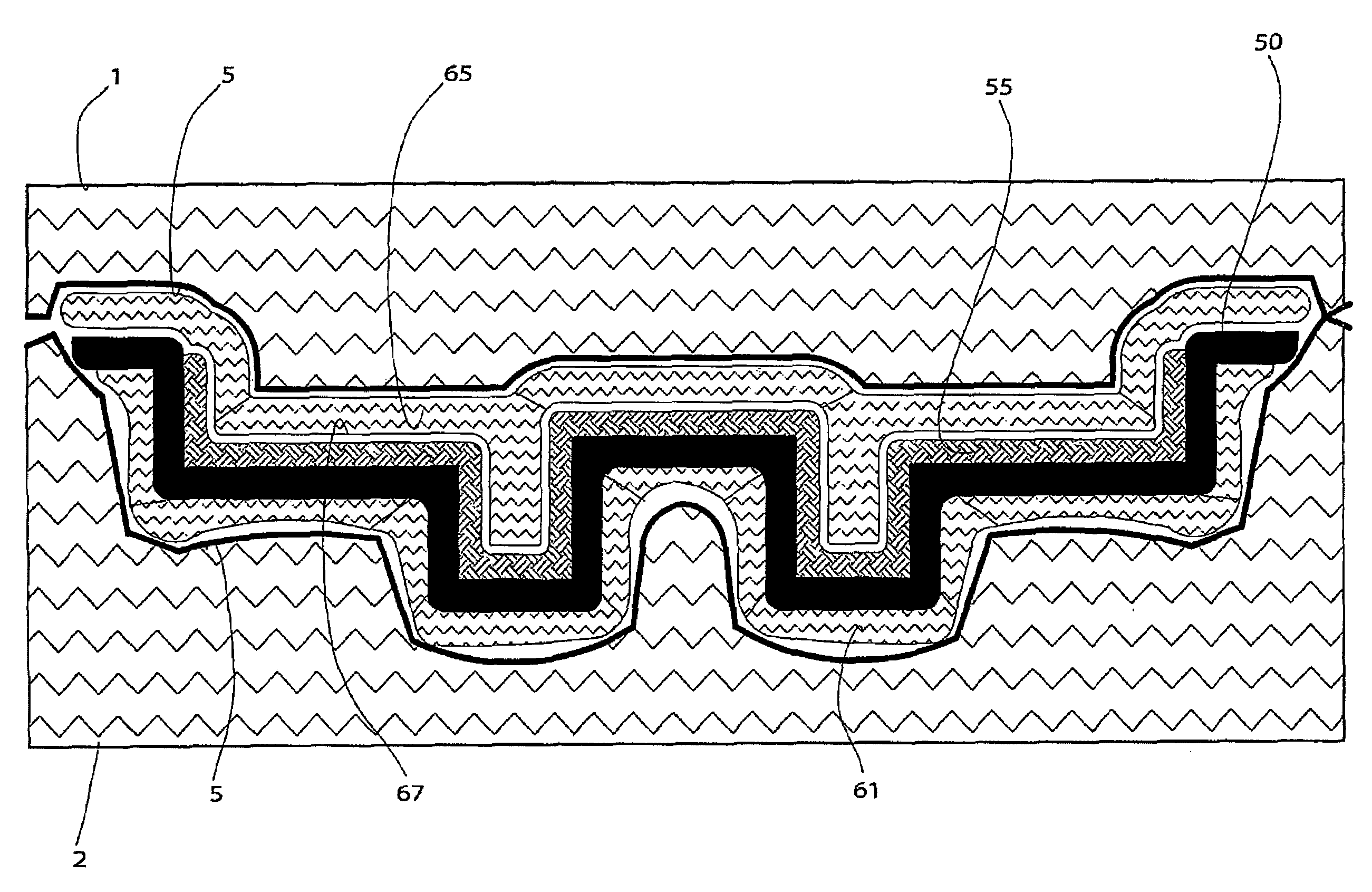
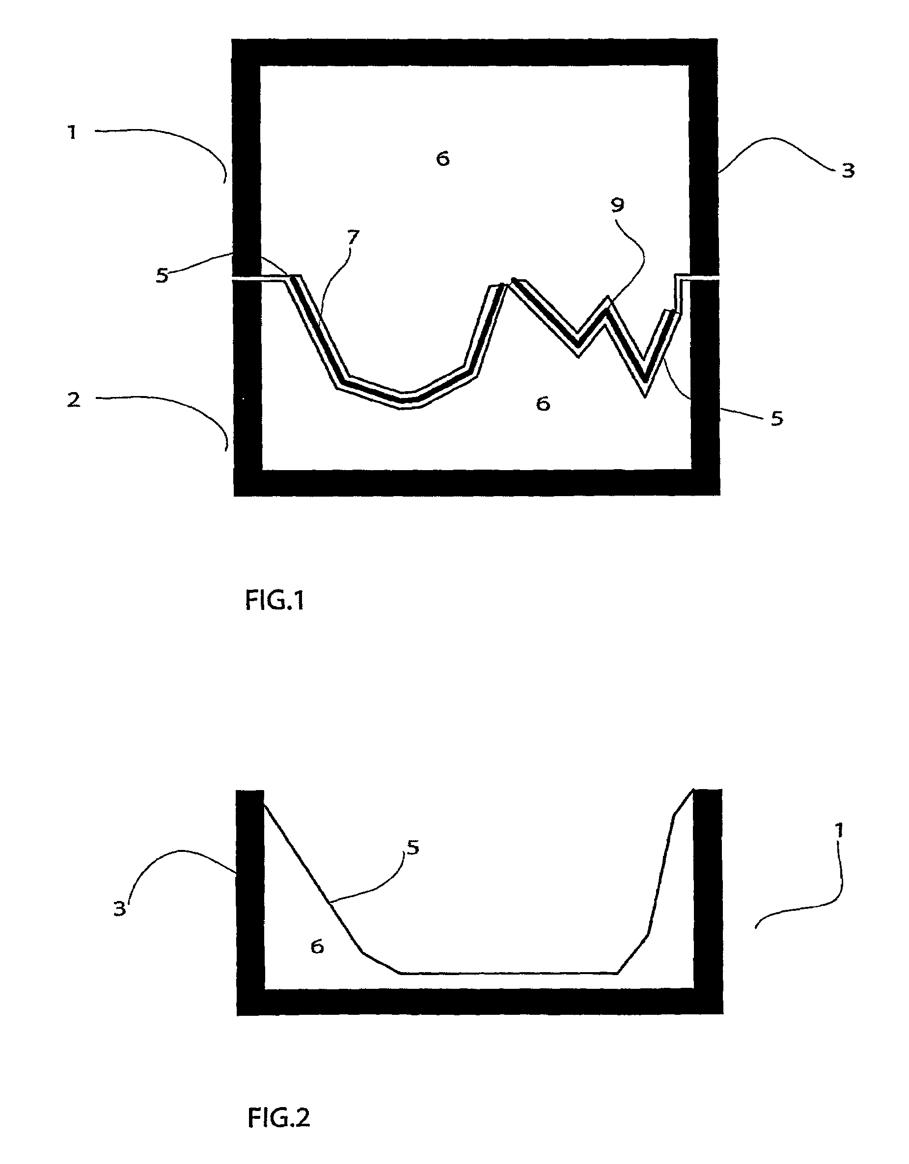
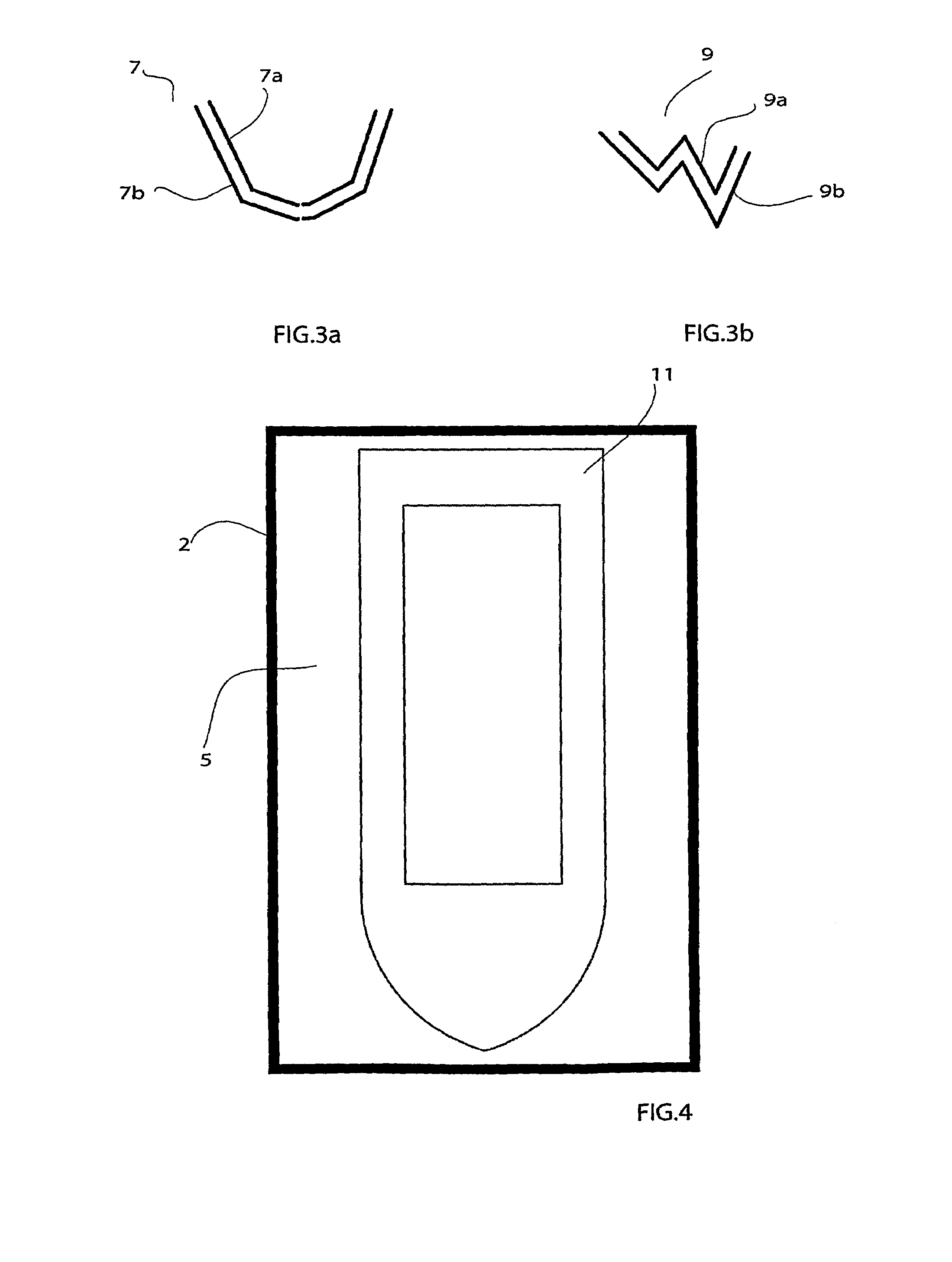
[0169]The composite components production system according to the present invention includes separate upper and lower pressure chambers 1, 2, one of said chambers being shown in FIG. 2. Each pressure chamber includes a main housing 3 supporting an elastically deformable and readily conformable chamber wall 5. The top pressure chamber 1 can be located over the bottom pressure chamber 2 with their respective elastically deformable and readily conformable chamber walls being located in opposing relation. Mould section assemblies 7, 9 can be located between the opposing chamber walls 5. Each mould assembly may typically include an upper mould section and lower mould section as for example shown in FIGS. 3a and 3b. FIG. 3a shows a mould assembly 7 for producing a boat hull including an upper mould section 7a and lower mould section 7b. A composite lay-up may be located between the upper and lower mould sections 7a, 7b. This composite lay-up may typically include resin impregnated materia...


PUM

PropertyMeasurementUnit
temperatureaaaaaaaaaa
temperaturesaaaaaaaaaa
pressureaaaaaaaaaa

Abstract

A system for producing composite or bonded metal components including: first and second pressure chambers, each pressure chamber having an elastically deformable chamber wall; means for circulating fluid at an elevated temperature and pressure through each said pressure chamber; and at least one mould assembly including at least one separate mould section providing a mould cavity within which a composite or bonded metal lay-up can be located; wherein when the system is in use, the pressure chambers are held together with the elastically deformable chamber walls located in opposing relation, the at least one mould assembly containing a said lay-up being accomodated between the chamber walls while fluid at elevated temperature and pressure is circulated through each pressure chamber such that the lay-up can be compressed and cured or formed.

Description

BACKGROUND OF THE INVENTION[0001]The present invention is directed to the manufacture of composite as well as super plastic forming and bonding of thin sheet metal components.[0002]Composite components are typically produced by impregnating a fibrous material such as fiberglass with a resin matrix or bonding medium such as thermoplastic or thermocuring resin, or forming and bonding sheets of thermoplastic material together or in layers to form parts. This resin impregnated material is subsequently subjected to an elevated pressure and temperature to compress the material and form or cure the resin matrix or bonding medium to thereby produce the composite / bonded component. Bonded metal components are formed by shaping the thin metal sheets and placing adhesive or bonding material between the sheets then elevating the temperature whilst maintaining a holding pressure or clamping force to ensure an adequate bond. In each case the material needs to be compressed to expel excess air and ...

Claims


Application Information

Patent Timeline
Patent Type & Authority Patents(United States)
IPC IPC(8): B29C43/02B29C43/20B29C43/10B29C35/00B29C43/12B29C70/44B29C70/54
CPCB29C35/007B29C43/12B29C70/443B21D26/021B21D26/059B29C70/542B29C33/04B29C33/405B29C2043/3238B29K2105/0854B29C70/44
Inventor GRAHAM, NEIL
Owner QUICKSTEP TECH
Why Eureka
Try Eureka