Thermal transient suppression material and method of production

a technology of thermal transient suppression and material, applied in the direction of energy input, semiconductor/solid-state device details, transportation and packaging, etc., can solve the problems of overheating and device failure, phase change materials have disadvantages for electronic applications, and expensive sealed containment is required, so as to reduce the volume of the matrix material, reduce the viscosity, and improve the thermal absorption characteristics of the ttsm

Inactive Publication Date: 2009-03-03
DELPHI TECH INC
View PDF18 Cites 5 Cited by
  • Summary
  • Abstract
  • Description
  • Claims
  • Application Information

AI Technical Summary

Benefits of technology

[0007]In one aspect of the invention, the thermal absorption characteristics of a TTSM may be improved by increasing the content of the filler particles. This may be accomplished by mixing a suitable thinner, such as Octamethyl trisiloxane, to the matrix material to reduce its viscosity before or during the addition of the fillers. The viscosity reduction allows more filler particles to be added to the matrix material. During the curing process, the thinner evaporates away, leaving only the matrix material and the fillers in the final product. The filler content of the cured TTSM may increase to about 97 weight % (with a thinner) from a maximum of 80 weight % (without a thinner). The thinner evaporation also reduces the volume of the matrix material, allowing for better particle-to-particle contact of the filler materials. This improves the thermal conductivity of the final material.
[0008]In another aspect of the present invention, a low-cost TTSM particularly useful for applications that generate thermal transients that are lower in power and longer in duration is provided. The method involves using a non-metallic organic fillers as a phase change thermal absorption component of the final material. The use of these non-electrically conductive organic materials eliminates the need for the phase change particle coating process, reduces the density of the final material, and reduces constituent material costs. Although the use of non-metallic phase change materials reduces the performance of the final TTSM, the performance of this new TTSM is still suitable for some applications and reduces the cost of the potting material.

Problems solved by technology

Heat generated by electronic devices during normal operation can cause overheating and device failure if not conducted away.
Each of these types of phase change materials has disadvantages for electronic applications.
Though solid-to-liquid phase change materials are capable of absorbing relatively large amounts of thermal energy, costly sealed containment is required to prevent loss of the material when in the liquid state.
Liquid-to-gas phase change materials are capable of absorbing even greater amounts of thermal energy, but the cost of containing the gas phase is typically higher than that for solid-to-liquid materials.
Another shortcoming is that solid-to-solid phase change materials are unable to provide an effective barrier to liquid and ionic contamination when used to encapsulate or pot electronic modules.

Method used


Image

  • Thermal transient suppression material and method of production
  • Thermal transient suppression material and method of production
  • Thermal transient suppression material and method of production

Examples


example 1

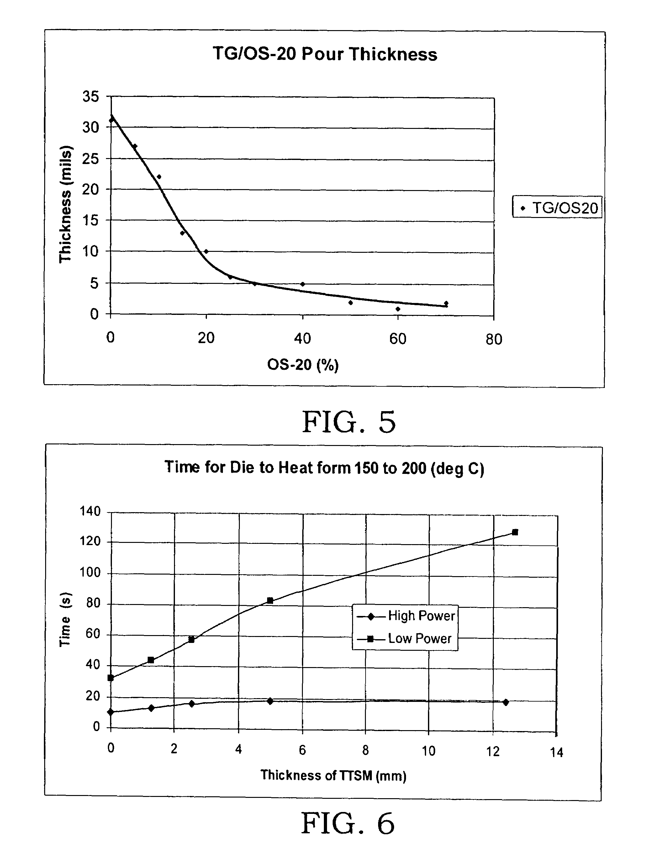
Effect of the Addition of OS-20 on Pour Thickness of TTSM

[0033]Experiments were performed by mixing different amounts of OS-20 to different batches of the matrix material (tough gel, TG) to reduce the viscosity of the matrix material. After the mixing was complete, the liquid gels were poured onto a substrate to solidify, and cure. The curing process took up to 4 to 6 hours if more OS-20 was added. At the end of the curing process, the thickness of the cured matrix material was measured. The measurement results are presented in FIG. 5. As shown, the more OS-20 was added to the matrix material, the thinner the cured final material was formed. Up to 70 weight % of OS-20 could be added to maintain an acceptable pour thickness of about 0.05 mm (0.002 in) or less.

example 2

Effect of Thickness of TTSM on Thermal Transient Performance

[0034]As shown in FIG. 6, TTSM prepared according to the process of the present invention was tested with two levels of power devices: low power (Steady State 12 W, Transient 36 W) and high power (Steady State 20 W and Transient 60 W). The results indicate that with the lower power, the thickness of TTSM had very little effect on the time required for the temperature of a die junction to change from 150° C. to 200° C. A thickness of 0.002 inch or 0.05 mm appeared to be optimal. With the high power, it appeared that the time required for the temperature of a die junction to change from 150° C. to 200° C. depended on the thickness of TTSM. The thicker the TTSM, the more the heat energy was absorbed, resulting in the longer time for the temperature to change to 200° C.

example 3

Thermal Properties of Two Formulations of TTSM

[0035]Two formulations of TTSM-1 and TTSM-2 were prepared according to the method of the present invention. TTSM-1 contained 6 weight % of the matrix material (TG), 13 weight % of boron nitride particles, and 81% of coated solder particles (6TG / 13BN / 81 Solder). TTSM-1 had solder particles having light coating (see Table 1). TTSM-2 had 4 weight % of the matrix material, 7 weight % of boron nitride particles, and 89% of coated solder particles (4TG / 7BN / 89 Solder). TTSM-2 had solder particles having heavy coating (see Table 1). TTSM-1 and TTSM-2 were tested with two power levels, a high power and a low power. The transient performance of TTSM-1 and TTSM-2 was determined and the results are reported in Table 2. The transient performance numbers represent the time required in seconds for the die junction temperature to rise from 150° C. to 200° C. The numbers in parentheses are the ratio of the observed times with TTSM material / without TTSM m...


PUM

PropertyMeasurementUnit
weight percentaaaaaaaaaa
thicknessaaaaaaaaaa
weight percentaaaaaaaaaa

Abstract

The present invention provides a high performance polymer-base material capable of dissipating transient thermal energy generated by an electronic module, such as a heat-generating power device. The methods of the present invention involve adding a suitable thinner to reduce the viscosity and increase the volume of a polymer-base matrix material so that a large amount of thermal absorbing particles may be added. The final cured product may have a filler content of more than 80 weight %. Further, the present invention provides a new and reduced cost formulation of a polymer-base thermal transient suppression material containing organic wax particles.

Description

TECHNICAL BACKGROUND[0001]1. Field of the Invention[0002]The present invention relates to methods and systems for managing / dissipating heat generated by electronic devices. More particularly, this invention relates to materials that absorb heat generated by transient thermal events.[0003]2. Description of the Related Art[0004]Heat generated by electronic devices during normal operation can cause overheating and device failure if not conducted away. While steady-state heat must be removed from the device and dissipated to the surrounding environment to prevent overheating, transient energy can be absorbed by the device and any surrounding packaging material and then dissipated to the environment more slowly. An example of a packaging material is a potting compound used to seal and protect a circuit device mounted on a circuit board within an open or closed case. Transient thermal energy can be absorbed with the use of packaging materials by two mechanisms. The first and most commonly...

Claims


Application Information

Patent Timeline
Patent Type & Authority Patents(United States)
IPC IPC(8): C08K5/01B05D7/00B32B5/16C09K5/06C09K5/14H01L23/373H01L23/427
CPCC09K5/063C09K5/14H01L23/3737H01L23/4275Y10T428/25H01L2924/0002H01L2924/00Y02P20/129
Inventor MYERS, BRUCE A.CHAUDHURI, ARUN K.
Owner DELPHI TECH INC
Why Eureka
Try Eureka