Semiconductor device
a technology of semiconductors and devices, applied in the field of semiconductor devices, can solve the problems of reducing the a/d conversion accuracy, and failure to perform appropriate testing, so as to suppress the influence of noise and suppress the circuit scale
- Summary
- Abstract
- Description
- Claims
- Application Information
AI Technical Summary
Benefits of technology
Problems solved by technology
Method used
Image
Examples
embodiment 1
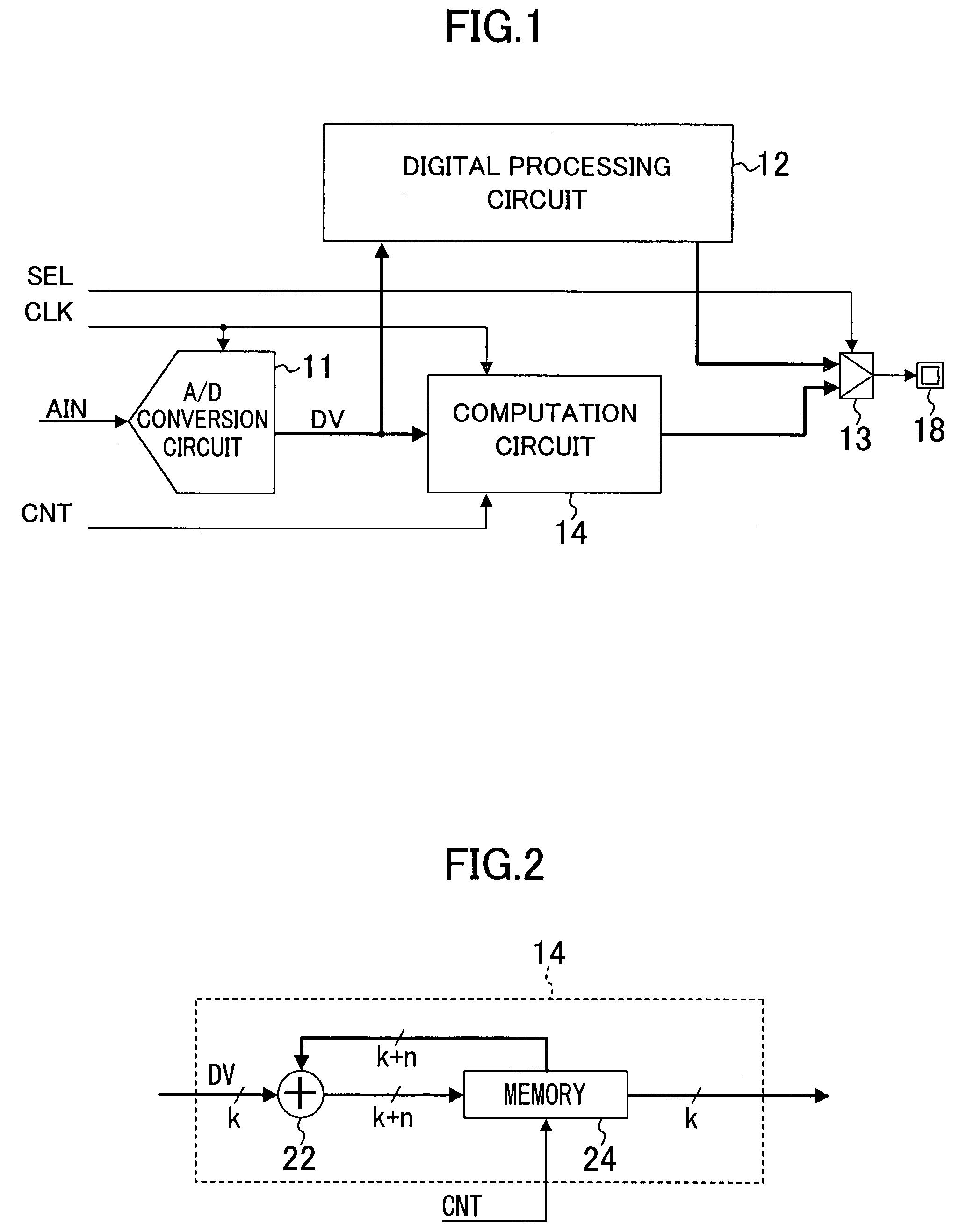
[0019]FIG. 1 is a block diagram of a semiconductor device of Embodiment 1 of the present invention. The semiconductor device of FIG. 1 includes an A / D conversion circuit 11, a digital processing circuit 12, a selector 13 and a computation circuit 14.
[0020]The A / D conversion circuit 11 A / D-converts an analog input signal AIN every clock cycle of a clock signal CLK supplied and outputs the result (A / D conversion result) to the digital processing circuit 12 and the computation circuit 14 as a digital signal DV. The clock signal CLK, the analog input signal AIN and a computation control signal CNT may be signals received from outside the semiconductor device of FIG. 1 or internal signals.
[0021]The digital processing circuit 12, which may be a logic circuit, for example, performs predetermined processing using the A / D conversion result from the A / D conversion circuit 11, and outputs the processed result to the selector 13.
[0022]The computation circuit 14 performs computation for the A / D ...
embodiment 2
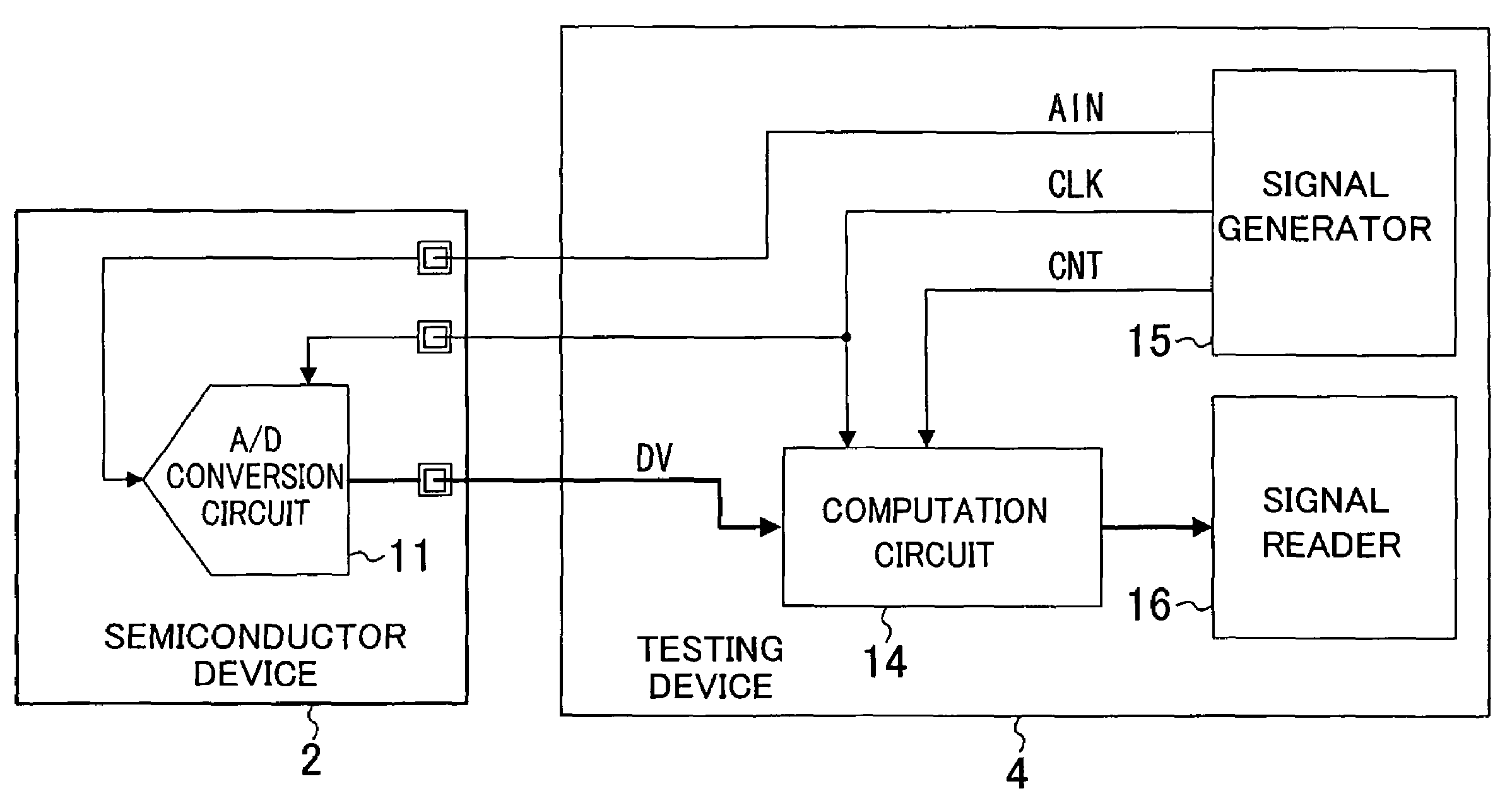
[0033]FIG. 4 is a block diagram of a testing device as a semiconductor device of Embodiment 2 of the present invention. A testing device 4 of FIG. 4 includes a computation circuit 14, a signal generator 15 and a signal reader 16. A semiconductor device 2 includes an A / D conversion circuit 11.
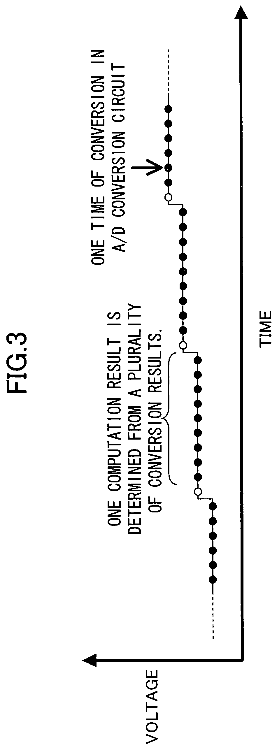
[0034]The signal generator 15 generates an analog input signal AIN and a clock signal CLK and outputs the generated signals to the A / D conversion circuit 11. The analog input signal AIN is similar to that described in Embodiment 1 and can be a signal as shown in FIG. 3, for example. The A / D conversion circuit 11 A / D-converts the analog input signal AIN every cycle of the clock signal CLK and outputs the conversion result to the computation circuit 14 as a digital signal DV.
[0035]Also, the signal generator 15 generates the clock signal CLK and a computation control signal CNT and outputs the generated signals to the computation circuit 14. The computation circuit 14 is similar to that described i...
embodiment 3
[0037]FIG. 5 is a block diagram of a semiconductor device of Embodiment 3 of the present invention. The semiconductor device of FIG. 5 includes an A / D conversion circuit 11 and a computation circuit 30. The computation circuit 30 includes an initial value memory 31, a subtractor 32, a difference value distribution circuit 33, a counter section 34, a difference detection circuit 36 and an adder 37. The counter section 34 includes (2j+1) counters ( is an integer equal to or more than 2). These counters respectively correspond to difference values j, j−1, . . . , 2, 1, 0, −1, −2, . . . , −j that can be outputted from the subtractor 32. The initial value memory 31 and all the counters in the counter section 34 are reset with a computation control signal CNT every time A / D conversion is performed m times.
[0038]FIG. 6 is a flowchart showing a flow of processing in the semiconductor device of FIG. 5. Referring to FIGS. 5 and 6, the processing in the semiconductor device of this embodiment ...
PUM
 Abstract
Description
Claims
Application Information
 - R&D
- Intellectual Property
- Life Sciences
- Materials
- Tech Scout
- Unparalleled Data Quality
- Higher Quality Content
- 60% Fewer Hallucinations
Browse by: Latest US Patents, China's latest patents, Technical Efficacy Thesaurus, Application Domain, Technology Topic, Popular Technical Reports.
© 2025 PatSnap. All rights reserved.Legal|Privacy policy|Modern Slavery Act Transparency Statement|Sitemap|About US| Contact US: help@patsnap.com


