
Circuit, method and program for data queue control

a data queue and circuit technology, applied in the field of circuits, methods and programs for controlling data queues, can solve the problems of reducing the circuit scale, reducing the circuit size, and avoiding the concentration of writing on a specific packet storage queue, so as to reduce the mounting footprint and costs, reduce the effect of reducing the footprint and avoiding the accumulation of writing

Inactive Publication Date: 2006-04-27
FUJITSU LTD
View PDF3 Cites 0 Cited by
  • Summary
  • Abstract
  • Description
  • Claims
  • Application Information

AI Technical Summary

Benefits of technology

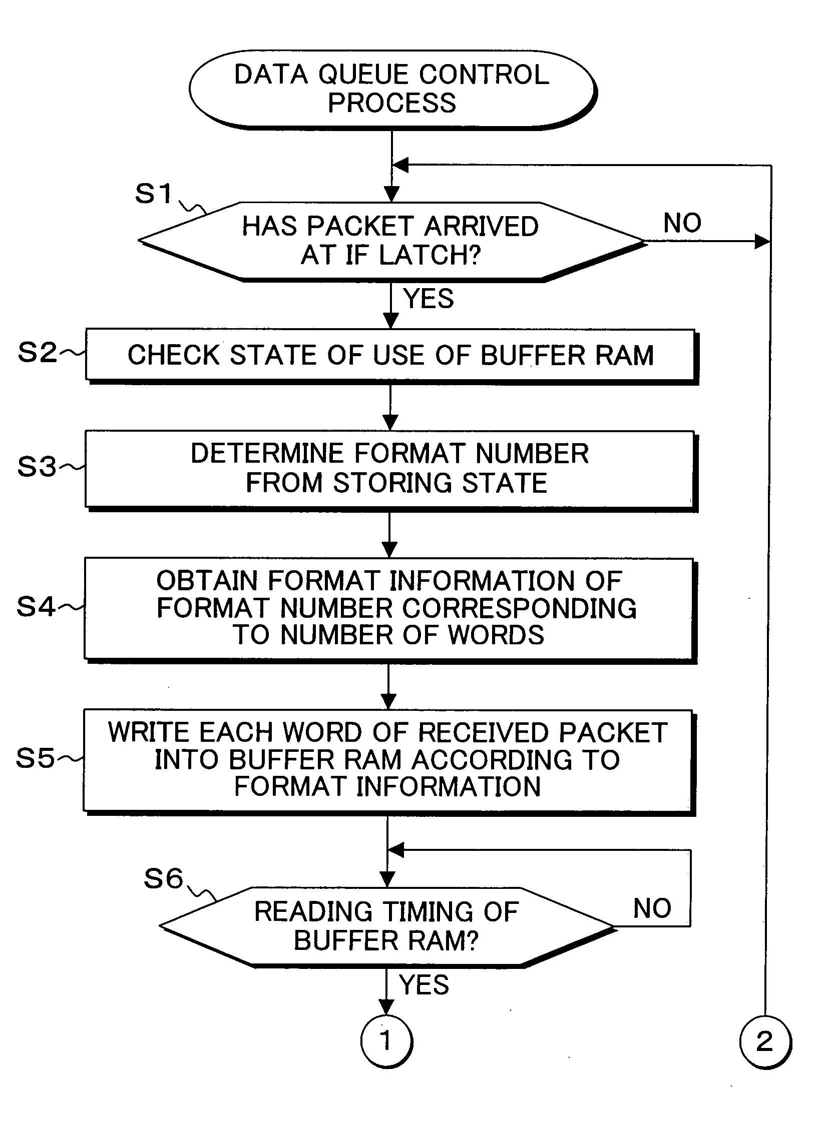
The present invention provides a data queue control circuit, method, and program for controlling data queues in a computer system. The invention minimizes the impact on circuit size and processing cycles by providing a buffer queue system with a limited number of buffer queues. The system includes a format determination circuit that dynamically determines a writing format for each buffer queue based on its availability. The data queues are then stored separately on a word by word basis, and a packet control circuit stores the received packets into the buffer queues based on the writing format. The system also includes a packet storage queue and a packet reading circuit for reading the packets from the buffer queues. The technical effects of the invention include improved data queue control and reduced impact on system performance.

Problems solved by technology

However, when the throughput of arrival of the packets is lower than the throughput of writing of the RAMs, cases where the writing into the RAMs can not catch up are present.
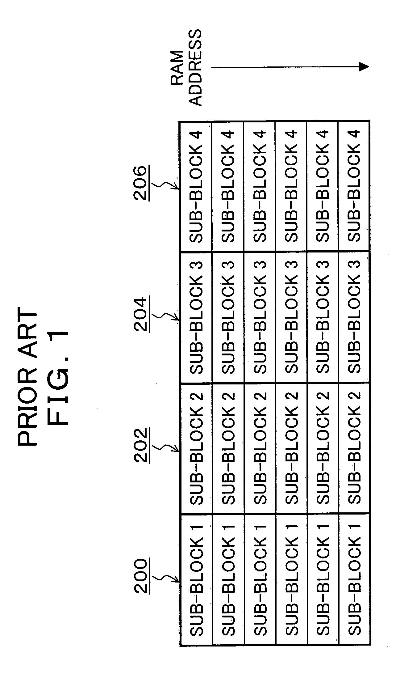
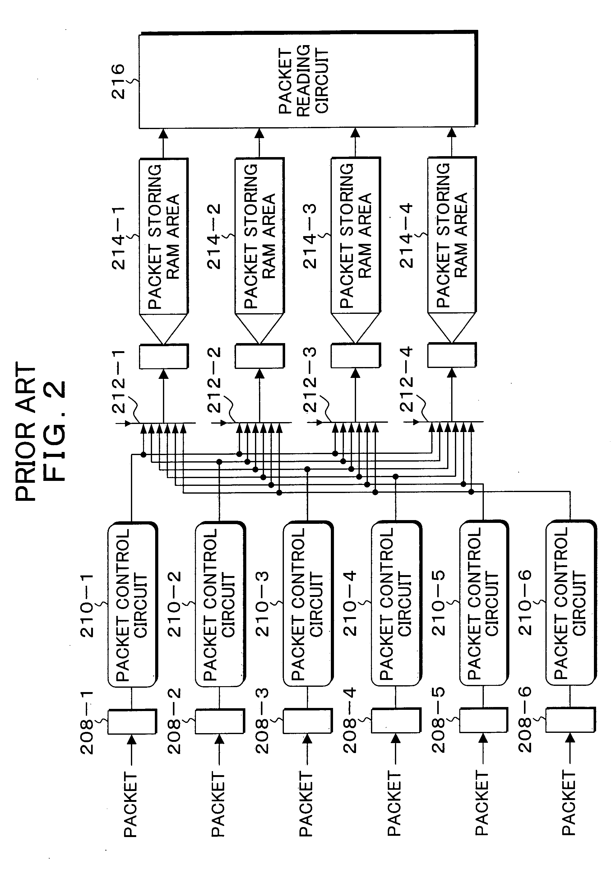
However, though such a data queue control method of FIG. 2 has no problem in the case where all of packet data of the amount of one (1) block is stored when packets are stored, that is, the case where all of the packet storage RAM areas 214-1 to 214-4 corresponding to the RAMs 200, 202, 204 and 206 deployed side by side are utilized, a problem arises that the packet storage RAM areas 214-1 to 214-4 deployed side by side can not be effectively utilized and the targets of the writing of the packets concentrate on a specific packet storage RAM area, therefore, the throughput of writing the packets into the RAMs can not be secured in the case where the length of the packets are various, packets having the length shorter than one (1) block are mixed and short packets arrive concentrating because data writing areas of the packets are limited.
Therefore the a problem that the circuit scale is considerably increased arises.
Furthermore, a problem that degradation of performance is caused to arise because the number of cycles from reception of the packets by the IF latches 208-1 to 208-6 to the writing of the packets into the packet storage RAM areas 214-1 to 214-4 is increased.

Method used


Image

  • Circuit, method and program for data queue control
  • Circuit, method and program for data queue control
  • Circuit, method and program for data queue control

Examples


Embodiment Construction

[0064]FIG. 4 is a block diagram of a system board in a computer system to which the present invention is applied. In FIG. 4, a system board 10 is provided with a system controller 12 and a data queue control circuit of the present invention is incorporated in the system controller 12. The system controller 12 is connected with CPUs 14-1 to 14-4 through packet buses 16-1 to 16-4. In addition, the system controller 12 is connected with memory controllers 18-1 and 18-2 and an I / O controller 20 through packet buses 26-1 to 26-3. The memory controllers 18-land 18-2 are connected with dual-in-line memory modules (DIMM) 22-1 and 22-2. The I / O controller 20 is connected with an I / O bus 24 and is connected with various input / output devices not shown including a magnetic disk sub-system, through the I / O bus 24. The system controller 12 receives packets transferred by each interface connected respectively with the memory controllers 18-1 and 18-2, the I / O controller 20 and the CPUs 14-1 to 14-...


PUM


Abstract

After packets received by receiving latches have been divided into individual words and the words have been stored into buffer queues, the packets read from the buffer queues are stored into packet storage queues. A format determining circuit has defined in advance a plurality of types of writing formats and, when a packet is received by any of the receiving latches, determines dynamically a writing format according to availability of the buffer queues at this time. Then, a packet control circuit divides the received packets into individual words and stores the words into the buffer queues, according to the determined writing format.

Description

CROSS-REFERENCE TO RELATED APPLICATION [0001] This application claims the benefit of priority from prior application No. JP 2004-307978, filed Oct. 22, 2004, in Japan. BACKGROUND OF THE INVENTION [0002] 1. Field of the Invention [0003] The present invention relates generally to a circuit, method and program for data queue control that store packets from a plurality of interfaces into the same data queue consisting of a plurality of RAMs, and more particularly, to a circuit, method and program for data queue control that avoid concentration of writing of packets to a specific queue by arranging a buffer queue in front of the RAMs. [0004] 2. Description of the Related Art [0005] Conventionally, in a processor board, etc. having a multi-CPU configuration, a system controller is arranged between a plurality of CPUs and resources such as memories and I / O buses, etc. After writing packets arrived from a plurality of interfaces positioned on the resource side into RAMs constituting a queue...

Claims


Application Information

Patent Timeline
Patent Type & Authority Applications(United States)
IPC IPC(8): H04J3/24H04L12/56H04L12/28G06F13/38
CPCH04L49/90H04L49/9026H04L49/9047
Inventor MISHIMA, MASAHIRO
Owner FUJITSU LTD
Learn More