Polarizer, projection lens system, exposure apparatus and exposing method

a projection lens and polarizer technology, applied in the field of exposure, can solve the problems of inability to improve the degree of resolution, the degradation of the imaging characteristics of the photoresist, and the neglect of polarization to become evident, so as to improve the contrast of optical images and improve the resolution characteristics

Inactive Publication Date: 2009-03-03
RENESAS ELECTRONICS CORP
View PDF8 Cites 19 Cited by
  • Summary
  • Abstract
  • Description
  • Claims
  • Application Information

AI Technical Summary

Benefits of technology

[0007]It is an object of the present invention to improve the contrast of an optical image generated in a photoresist, and therefore to improve resolution characteristics.
[0009]The polarizer is disposed with its center lying on the center of the surface of the pupil of a projection lens system in an exposure apparatus, thereby transmitting s-polarized light of illumination light in the exposure apparatus while cutting off p-polarized light. Thus, exposure using light which has passed through the polarizer can improve the contrast of an optical image, and hence, resolution characteristics can be improved.
[0011]Therefore, variations in exposure characteristics of an exposure apparatus can be reduced, even when an increase in the numerical aperture of the projection lens system widens the range of distributions of the angle of incidence.
[0013]Therefore, exposure using s-polarized light of illumination light can improve the contrast of an optical image, and hence, resolution characteristics can be improved.
[0015]S-polarized light of illumination light is transmitted at exposure, while p-polarized light is cut off. Therefore, exposure using light which has passed through the polarizer can improve the contrast of an optical image, and hence, resolution characteristics can be improved.

Problems solved by technology

However, as NA is getting higher, the angle of incidence on a target of exposure, e.g., a photoresist increases, which causes the effects of polarization which have been neglected to become evident.
This causes degradation in imaging characteristics in the photoresist.
Then, improvement in the degree of resolution cannot be expected even where NA is increased.

Method used


Image

  • Polarizer, projection lens system, exposure apparatus and exposing method
  • Polarizer, projection lens system, exposure apparatus and exposing method
  • Polarizer, projection lens system, exposure apparatus and exposing method

Examples


first preferred embodiment

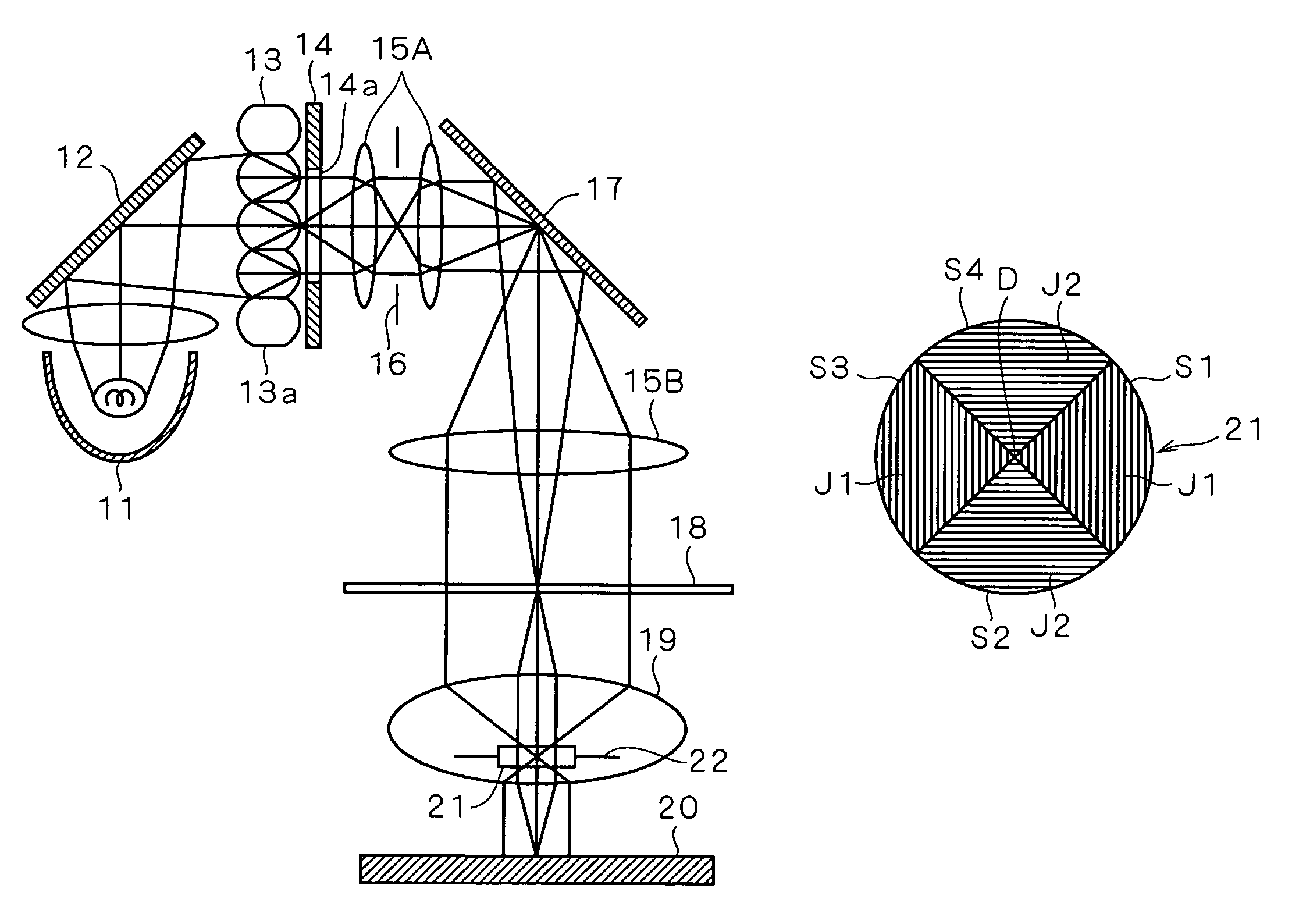
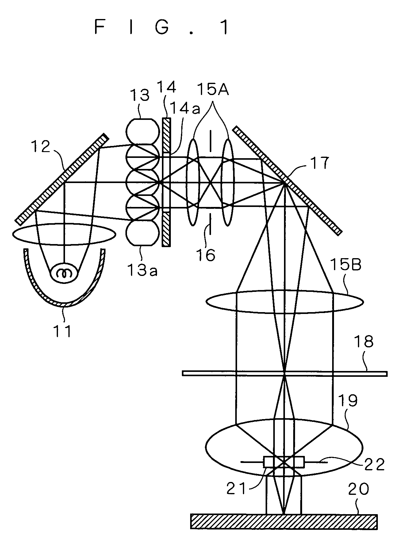
[0027]FIG. 1 shows an optical system of a projection exposure apparatus to which the present invention is applicable. Illumination light emanated from a lamp house 11 is reflected off a mirror 12, and passes through a fly eye lens 13, an aperture member 14, a relay lens 15A and a blind 16 in this order, and is further reflected off a mirror 17.

[0028]The fly eye lens 13 is divided into a plurality of lens regions 13a, and light emitted from the respective lens regions 13a pass through an opening of the aperture member 14. On the surface of a photomask 18, the light rays from the individual lens regions 13a are laid on top of one another, which means the lens regions 13a contribute to uniform illumination.

[0029]The illumination light reflected off the mirror 17 reaches the photomask 18 with a circuit pattern formed thereon, through a condenser lens 15B. The light which has passed through the photomask 18 (including diffracted light) passes through a projection lens system 19 to reach ...

second preferred embodiment

[0041]In the present embodiment, another mode of the polarizer 21 will be described, by way of example. FIG. 9 illustrates a pattern on the photomask 18. In the pattern, a plurality of light shielding portions 18a extending in one direction are arranged at intervals in parallel to one another. Light incident on the photomask 18 passes through the intervals, while the light shielding portions 18a shield the incident light.

[0042]FIG. 10 schematically shows the behavior of diffracted light generated by the photomask 18, seen in a direction parallel to that in which the light shielding portions 18a extend.

[0043]Incident light Li, after passing through the intervals between the light shielding portions 18a, is split into zero-order diffracted light L0 and first-order diffracted light L1 (or higher-order diffracted light). Since the light shielding portions 18a extend in one direction, the diffracted light has the direction of polarization having a component parallel to that of the extend...

third preferred embodiment

[0047]FIG. 12 schematically shows the directions of amplitude J1 and J2 of light passing through the polarizer 21 according to the present embodiment. The polarizer 21 is equally divided in to four regions S1 to S4 centering at a position D. The direction of amplitude J1 of polarized light passing through the regions S1 and S3 facing each other and the direction of amplitude J2 of polarized light passing through the regions S2 and S4 facing each other are perpendicular to each other.

[0048]Therefore, where there exist two pairs of light shielding portions in the pattern on the photomask 18, each pair extending in one direction, and the extending directions of the two pairs cross each other at 90 (=360 / 4) degrees, the same effects as in the second preferred embodiment can be achieved. When disposing the polarizer 21 on the surface of the pupil 22a (FIG. 6), it is preferable that the directions of amplitude J1 and J2 and the extending directions of the two pairs of light shielding port...


PUM

PropertyMeasurementUnit
angle of incidenceaaaaaaaaaa
angleaaaaaaaaaa
imaging characteristicsaaaaaaaaaa

Abstract

The directions of amplitude of polarized light passing through a polarizer are concentric around a position. The polarizer is disposed on the surface of a pupil such that the position lies exactly on the center of the surface of the pupil. Rays of luminous flux of illumination light converted into polarized light by the polarizer are converged onto a wafer with concentric planes of polarization with respect to an optical axis. The illumination light is therefore incident on a photoresist as s-polarized light. Thus, the amount of light entering the photoresist is less likely to depend upon the angle of incidence. Consequently, the contrast of an optical image formed in the photoresist is improved, and hence, resolution characteristics are improved.

Description

BACKGROUND OF THE INVENTION[0001]1. Field of the Invention[0002]The present invention relates to a technique for manufacturing a semiconductor device, and more particularly to a technique for exposure.[0003]2. Description of the Background Art[0004]Semiconductor devices are continuously becoming miniaturized, and the numerical aperture (NA) of exposure apparatuses is being increased for further miniaturization.[0005]However, as NA is getting higher, the angle of incidence on a target of exposure, e.g., a photoresist increases, which causes the effects of polarization which have been neglected to become evident. This causes degradation in imaging characteristics in the photoresist. Such circumstances are introduced in “Challenges in high NA, polarization, and photoresists” by Bruce W. Smith, et al., SPIE 2002, 4691-2, pp. 11-24. The following documents are related to the present invention: “Polarizing & Retardation Films” retrieved on May 15, 2003 from the Nitto Denko homepage <UR...

Claims


Application Information

Patent Timeline
Patent Type & Authority Patents(United States)
IPC IPC(8): G03B27/72G02B5/30G03F7/20H01L21/027
CPCG03B27/72G03F7/70308
Inventor YAMADA, TETSUYAUENO, LEGAL REPRESENTATIVE, RITSUKOOKAGAWA, TAKASHIUENO, ATSUSHI
Owner RENESAS ELECTRONICS CORP
Why Eureka
Try Eureka