Method for the active damping of the drive train in a wind energy plant

a technology of wind energy plant and drive train, which is applied in the direction of motors, engine control, engine fuctions, etc., can solve the problems of grid errors, disturbances at the generator side, etc., and achieve the effect of avoiding high stresses on the drive train and its components

Inactive Publication Date: 2009-03-10
NORDEX ENERGY
View PDF6 Cites 12 Cited by
  • Summary
  • Abstract
  • Description
  • Claims
  • Application Information

AI Technical Summary

Benefits of technology

[0011]In one preferred embodiment, the oscillatory delay element has a predetermined natural oscillation frequency which is at least 8%, preferably 12% smaller than the smallest natural frequency occurring at the drive train. Through the selection of the predetermined natural oscillation frequency on the oscillatory delay element, it is made sure on the one hand that changes of the rotational speed, which occur through wind gustings or through the intervention of a pitch system, for instance, do not lead to the generation of a correction moment for the generator control unit. On the other hand, through the selection of the natural oscillation frequency it is made sure that resonance vibrations are damped in time and too high stresses for the drive train and its components are avoided.

Problems solved by technology

First of all, circulation periodic disturbances are a possibility, like tower wind shelter or tower dam, height profile of the wind speed, skew upwind of the rotor through yaw angles or skew axis inclinations and / or unbalanced masses of the rotor blades.
Besides to the outer excitations, which occur as multiples of the rotor's rotational speed, disturbances at the generator side also occur, like grid errors, electric grid oscillations at very long grid feed lines, oscillations of converters and DC intermediate circuits, control influences and consumer retroaction in the isolated operation.

Method used


Image

  • Method for the active damping of the drive train in a wind energy plant
  • Method for the active damping of the drive train in a wind energy plant
  • Method for the active damping of the drive train in a wind energy plant

Examples


Embodiment Construction

[0016]While this invention may be embodied in many different forms, there are described in detail herein a specific preferred embodiment of the invention. This description is an exemplification of the principles of the invention and is not intended to limit the invention to the particular embodiment illustrated

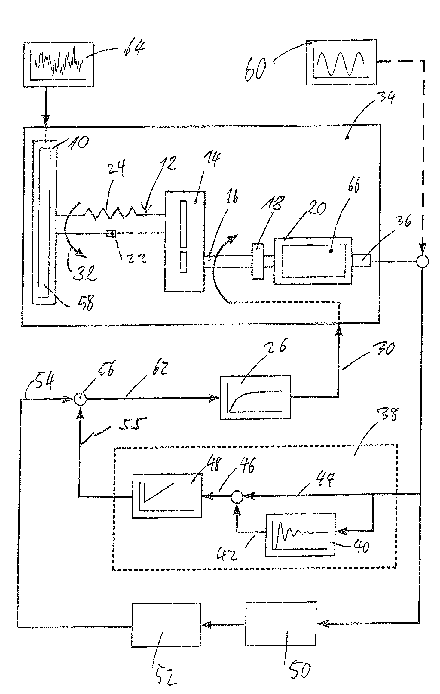
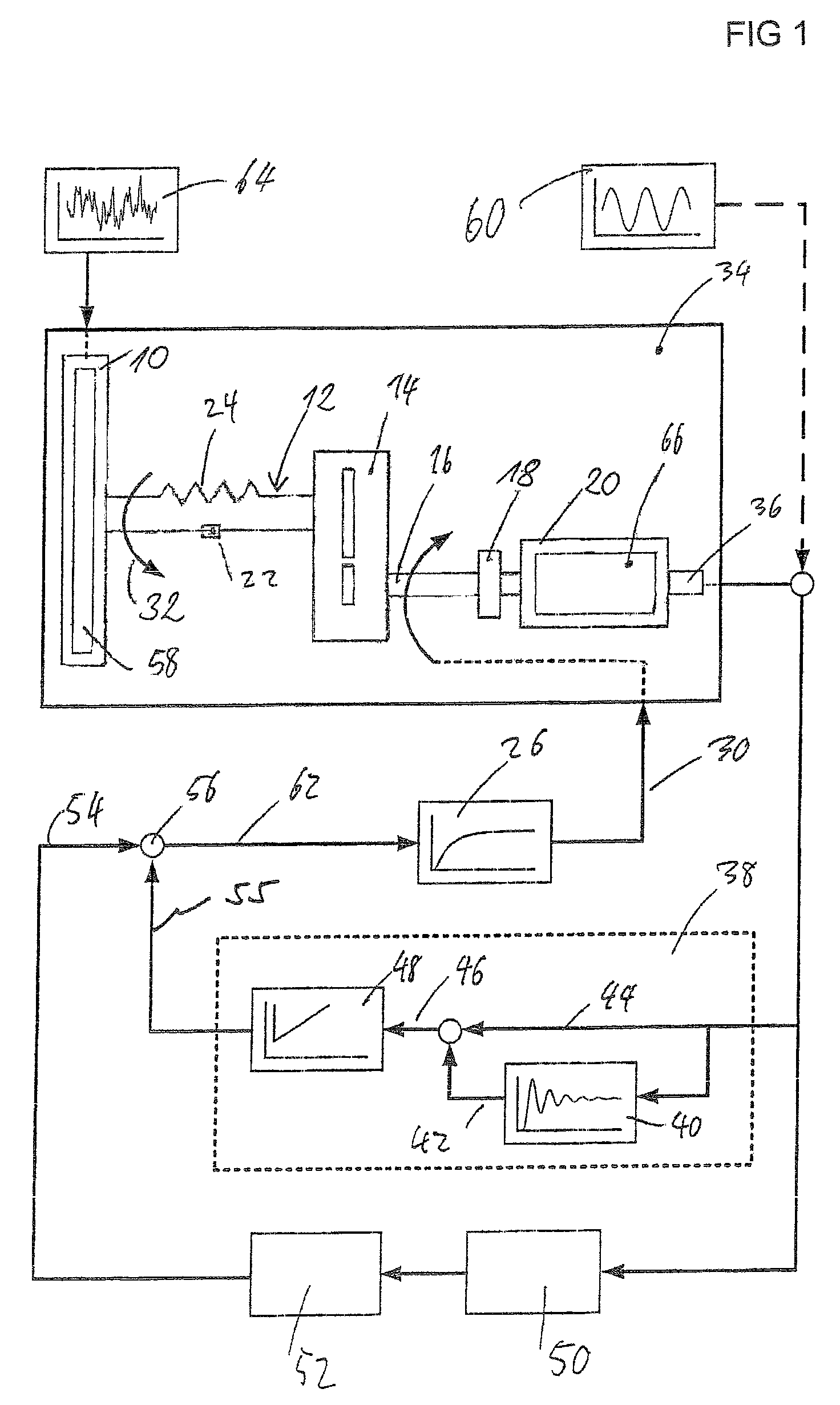
[0017]FIG. 1. shows the configuration of essential elements of the drive train 34 of a wind energy plant in an overview. The rotor, consisting of rotor blades and a rotor hub housing is schematically represented with 10. Through the action of the wind 64 on the rotor 10, a rotor torque 32 is generated and the rotor side shaft 12 is driven. The rotor shaft 12 runs out into a gearbox 14, the output shaft of which is called the generator shaft 16. The generator shaft 16 is connected with an input shaft of the generator 20 via a coupling 18. For the sake of better understanding of the occurring vibrations on the drive train, the rotor shaft can be assumed to be elastic, which is r...


PUM


Abstract

A method for the active damping of a drive train in wind energy plant, with the following steps: the actual value of the generator rotational speed is acquired and amplified via an oscillatory delay element, the oscillatory delay element has a predetermined natural oscillation frequency (ωE), which is smaller than the smallest natural frequency of the drive train, and a difference between the actual value of the rotational speed and the amplified value for the rotational speed is connected to a controller as actuating variable, which determines a correction moment for a generator control.

Description

CROSS-REFERENCE TO RELATED APPLICATIONS[0001]Not applicable.STATEMENT REGARDING FEDERALLY SPONSORED RESEARCH[0002]Not applicable.BACKGROUND OF THE INVENTION[0003]The present invention is related to a method for the active damping of vibrations on and / or in a drive train of a wind energy plant.[0004]With drive train is usually meant the assembly of rotor, rotor shaft (slow shaft), gearbox, generator shaft (fast shaft), coupling and generator. For wind energy plants, it is commonly known that the vibration excitations of the drive train may have different causes. First of all, circulation periodic disturbances are a possibility, like tower wind shelter or tower dam, height profile of the wind speed, skew upwind of the rotor through yaw angles or skew axis inclinations and / or unbalanced masses of the rotor blades. Besides to the outer excitations, which occur as multiples of the rotor's rotational speed, disturbances at the generator side also occur, like grid errors, electric grid osc...

Claims


Application Information

Patent Timeline
Patent Type & Authority Patents(United States)
IPC IPC(8): H02P9/44
CPCF03D7/0272F03D7/0292F03D7/044F03D11/02F05B2260/96F05B2270/327Y02E10/722Y02E10/723F03D15/00F03D15/10F03D80/00Y02E10/72
Inventor LAUBROCK, MALTEWOLDMANN, THOMAS PAULBILGES, SOREN
Owner NORDEX ENERGY
Why Eureka
Try Eureka