Method and apparatus for enhanced packaging for PC security

a technology for enhancing packaging and pc security, applied in the direction of circuit security details, electrical apparatus construction details, printed circuit aspects, etc., can solve problems such as substantial barriers to removal, and achieve the effect of high value or security-related components

Inactive Publication Date: 2011-08-16
MICROSOFT TECH LICENSING LLC
View PDF18 Cites 1 Cited by
  • Summary
  • Abstract
  • Description
  • Claims
  • Application Information

AI Technical Summary

Benefits of technology

A socket may be adapted to allow the versatility of late stage manufacturing or for protection during soldering operations while also helping to ensure that high value or securit

Problems solved by technology

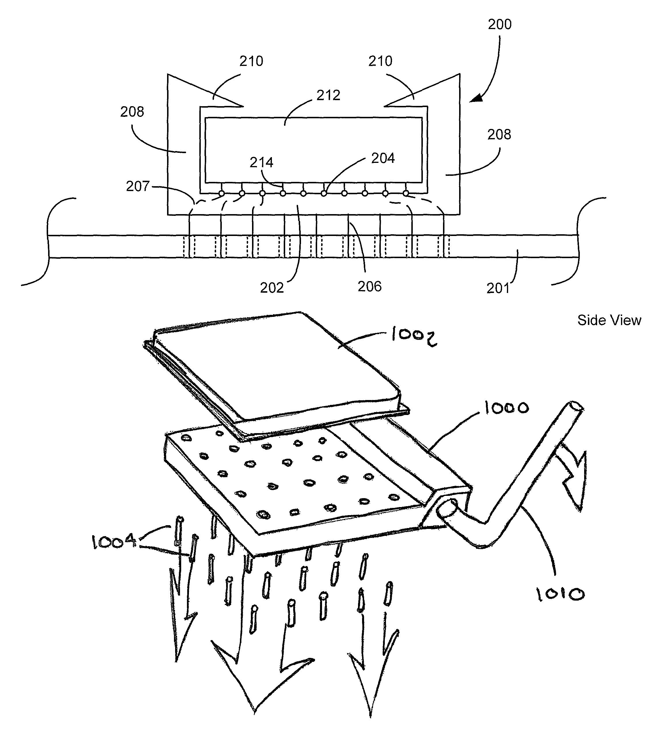
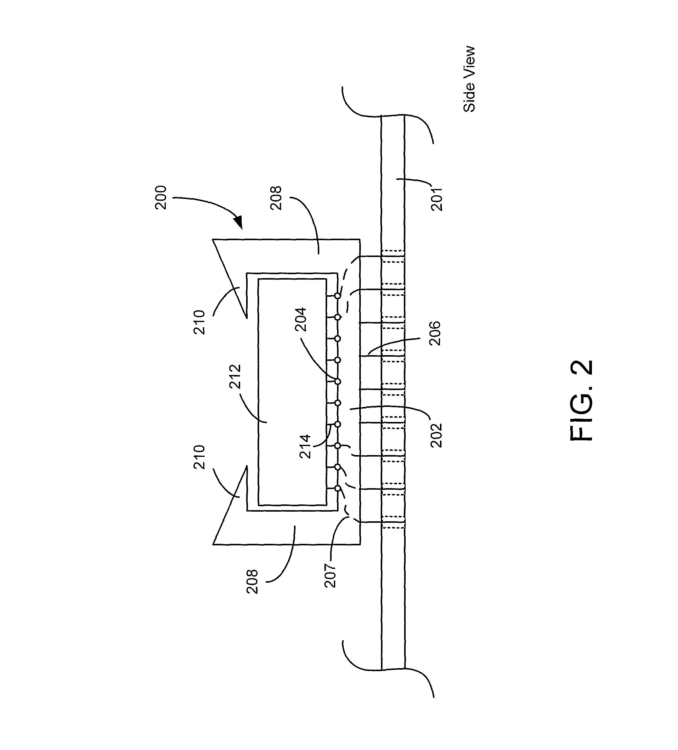
In one embodiment, a socket with a sidewall and barb may a

Method used


Image

  • Method and apparatus for enhanced packaging for PC security
  • Method and apparatus for enhanced packaging for PC security
  • Method and apparatus for enhanced packaging for PC security

Examples


Embodiment Construction

Although the following text sets forth a detailed description of numerous different embodiments, it should be understood that the legal scope of the description is defined by the words of the claims set forth at the end of this disclosure. The detailed description is to be construed as exemplary only and does not describe every possible embodiment since describing every possible embodiment would be impractical, if not impossible. Numerous alternative embodiments could be implemented, using either current technology or technology developed after the filing date of this patent, which would still fail within the scope of the claims.

It should also be understood that, unless a term is expressly defined in this patent using a sentence that begins “As used herein” and finishes with, “is hereby defined to mean . . . ” or a similar sentence that defines the term, there is no intent to limit the meaning of that term, either expressly or by implication, beyond its plain or ordinary meaning, an...


PUM


Abstract

A method having a socket for coupling signals between an electrical component and a circuit board or equivalent has a mechanism that, when activated, attaches the electrical component to the socket so that it is not possible to remove the electrical component without damaging it. The mechanism may include a clamshell lid with a one-time locking mechanism, a pin contact mechanism that, after initial locking, will detach the pins of the electrical component if further disturbed, or a moat around the base of the electrical component for disposing an epoxy fastener. The moat may include a heating element to cure the epoxy or other glue. The socket may include an electrical component that allows detection of tampering with the socket.

Description

BACKGROUNDSockets are used on circuit boards, for many reasons, including to allow replacement of defective parts and to protect heat-sensitive parts during waveline or other-style soldering operations. The socket is attached to the circuit board, flexible strip, ceramic or other substrate. Then, either in a late manufacturing operation or field customization process, the electrical component may be added to the socket. Later, the component may be removed and replaced, either when found defective or to upgrade performance.Sockets vary by size and type. Some sockets have friction-fit lead receivers, usually for lower pin-count sockets, to keep insertion easy. Higher pin count chips may use a zero-insertion force socket, where the electrical component is placed in open holes in the socket and a clamping arrangement pushes contacts against respective pins. The electrical component is held in place by the friction force of the clamp.In many applications, a high-value component or a secu...

Claims


Application Information

Patent Timeline
CPCH05K3/301H05K7/1092H05K1/0275H05K2201/10325
Inventor SCHMIDT, SHONTEMPLE, NICHOLASJENKINS, KURT A.LENNON, THOMAS PATRICKLANE, DAVID MICHAEL
Owner MICROSOFT TECH LICENSING LLC
Why Eureka
Try Eureka