
Method and device for generating a signal by fractional frequency locked loop

a fractional frequency and loop technology, applied in the field of frequency synthesis, can solve the problems of limiting the number of frequencies that can be addressed on the basis of a single reference frequency, causing noise that has to be apportioned, and raising big noise problems, so as to reduce the digital part, avoid dead areas, and reduce the current consumption

Inactive Publication Date: 2009-03-10
STMICROELECTRONICS SRL
View PDF6 Cites 0 Cited by
  • Summary
  • Abstract
  • Description
  • Claims
  • Application Information

AI Technical Summary

Benefits of technology

"The invention provides a frequency synthesis method that combines the benefits of locked loops with those of fractional phase locked loops. The method uses a measurement phase and a correction phase to address the limitations of conventional locked loops. The method allows for stable frequency synthesis with low noise and reduced frequency intervals. The invention also includes a device for generating a desired signal with a desired frequency. The device includes a controlled oscillator, a divider unit, a determination unit, a transfer unit, a sampler / integrator, and a controller or control means. The technical effects of the invention include improved stability, reduced noise, and improved accuracy in frequency synthesis."

Problems solved by technology

Their limitation stems from the fact that only the synthesis of integer multiples is possible, thereby limiting the number of frequencies that can be addressed on the basis of a single reference frequency.
This type of architecture, which solves the problem of decimal part division, nevertheless raises big noise problems.
These repeated injections of current give rise to noise that has to be apportioned.
Additionally, these lines may render the circuit inoperative if they do not comply with the specifications regarding the noise around the fundamental.
Thus, for very long sequences, the parasitic lines are akin to noise apportioned about the frequency generated, on account of undesired modulation of the output frequency.
The system is therefore complex.

Method used


Image

  • Method and device for generating a signal by fractional frequency locked loop
  • Method and device for generating a signal by fractional frequency locked loop
  • Method and device for generating a signal by fractional frequency locked loop

Examples


Embodiment Construction

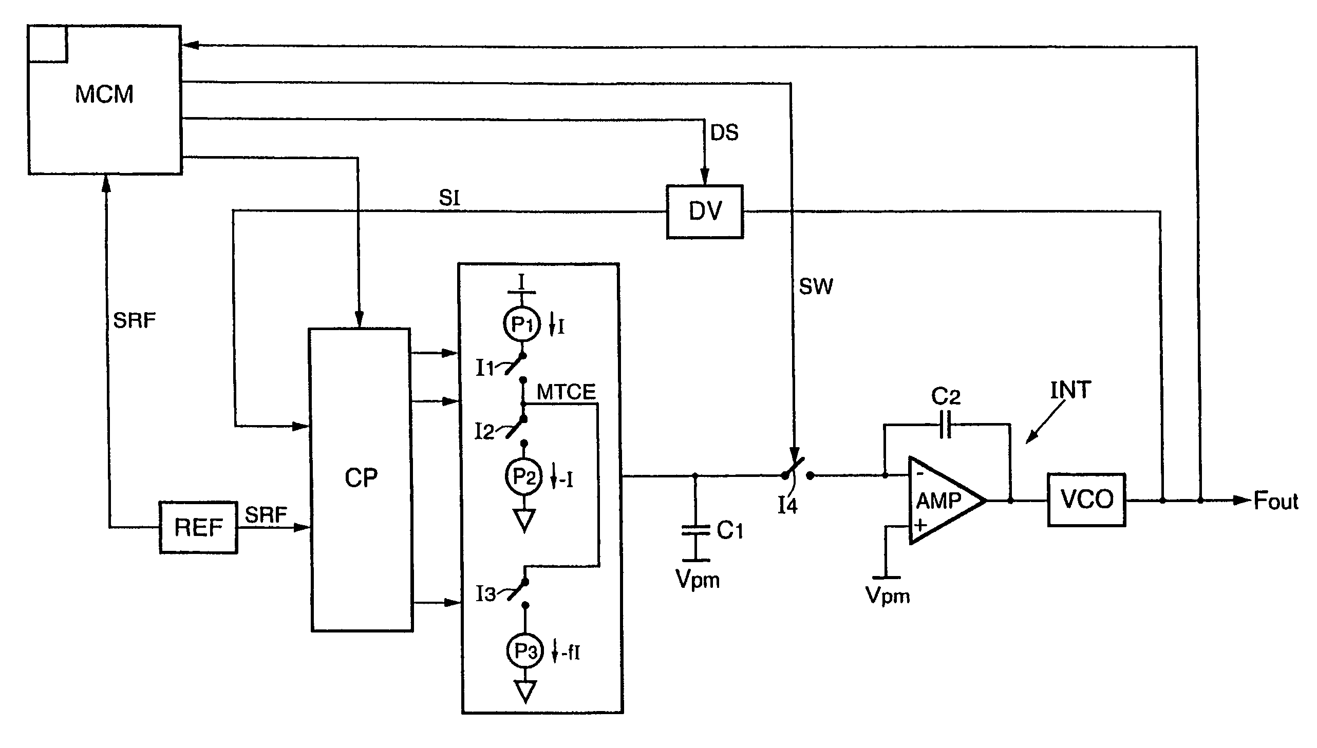
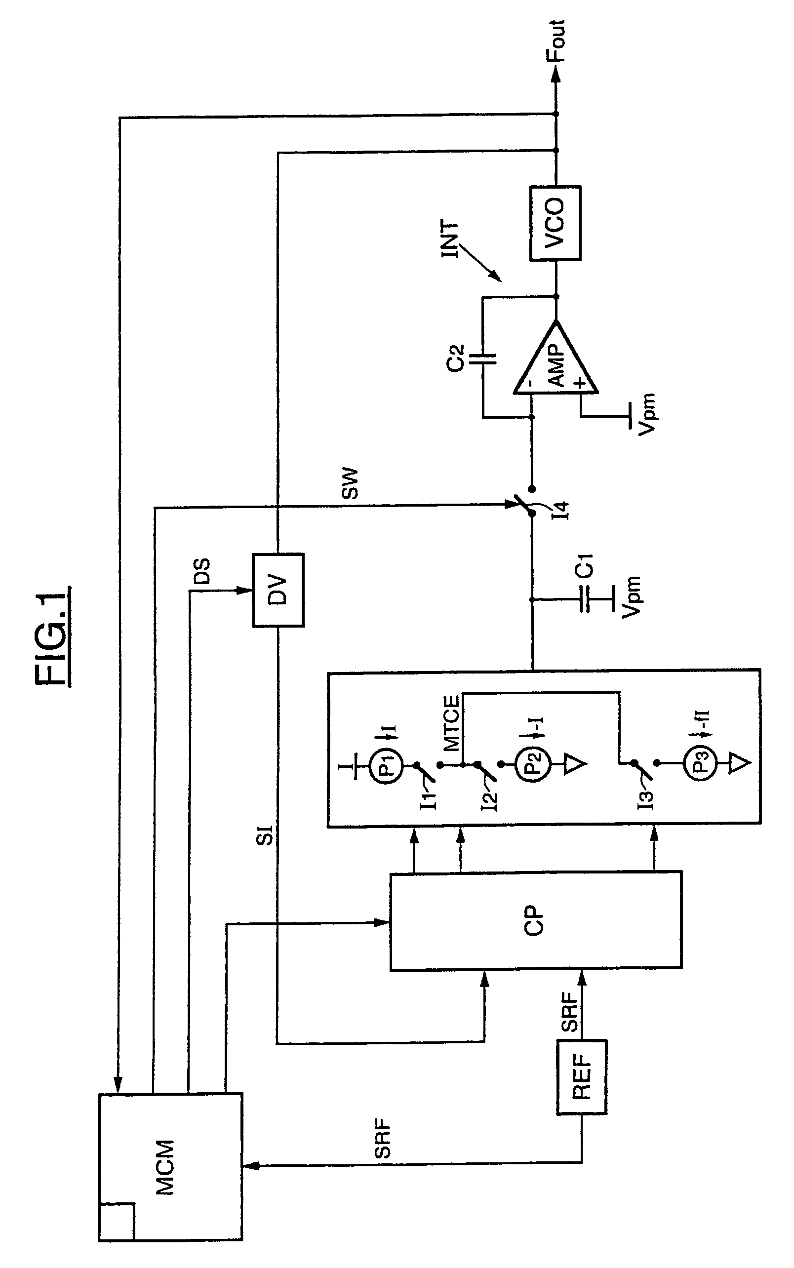
[0038]Referring initially to FIG. 1, an embodiment of a frequency synthesizer device is represented. This device comprises a voltage-controlled oscillator VCO whose output delivers the desired output signal, in this instance the signal Fout. Although a voltage-controlled oscillator has been represented here, any type of controlled oscillator is suitable, for example a current-controlled oscillator.

[0039]The frequency synthesizer device comprises a divider DV capable of performing an integer division, in this instance by N, of the output signal delivered by the oscillator VCO. The divider DV can consist of a counter up to N. This first intermediate signal SI, delivered by the divider DV is provided to determination unit or means of determination CP. Furthermore, the divider DV may be activated or deactivated by a logic signal DS delivered by the controller or control means MCM. Moreover, the determination unit or means of determination CP receives a reference signal SRF, having a ref...


PUM


Abstract

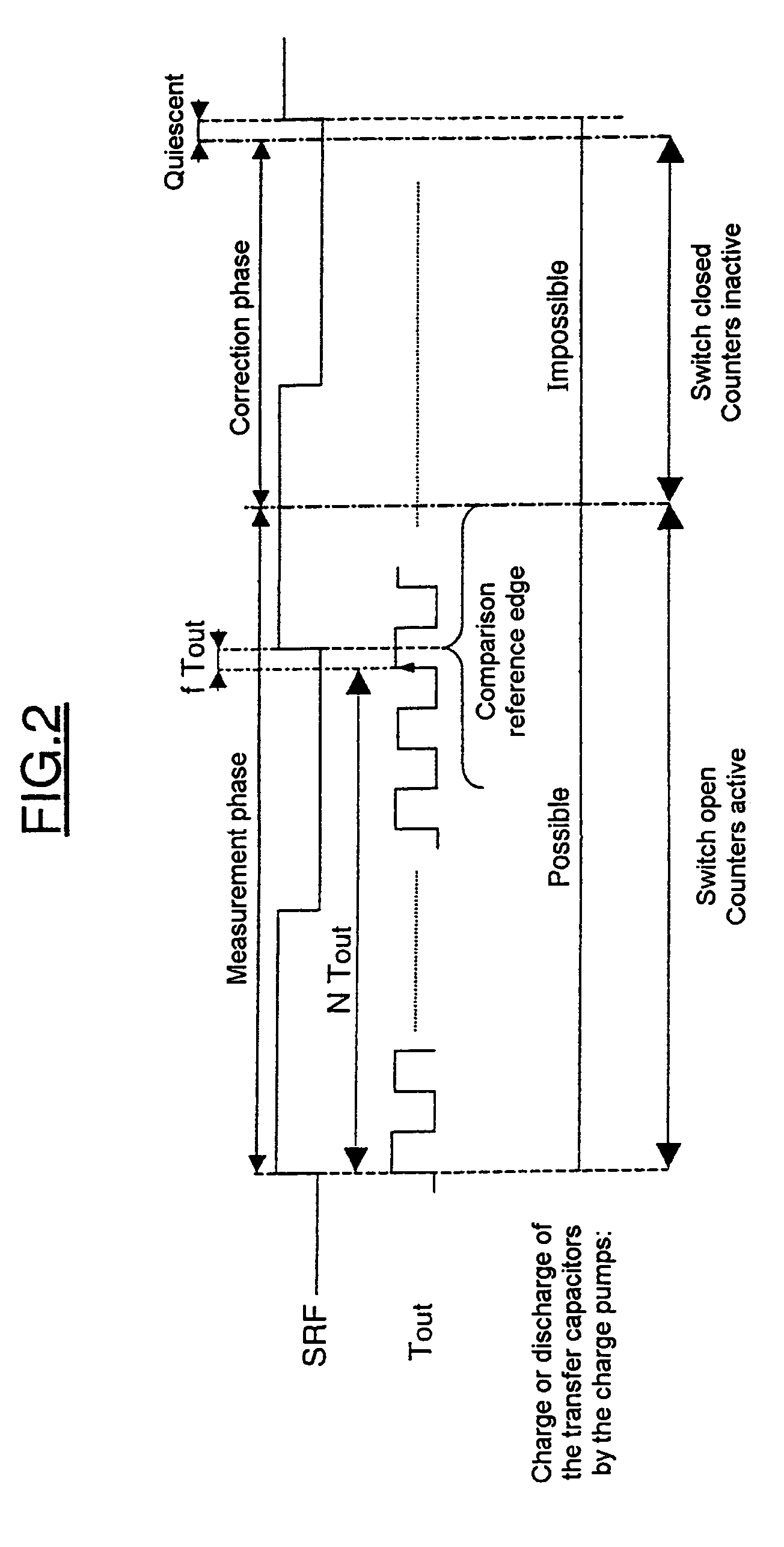
A method in accordance with the invention may include a cyclical succession of measurement phases and of correction phases. The correction phase may include a deactivation of a frequency divider and a correction of the control of an oscillator on the basis of the error signal, with the output signal from the oscillator forming the desired signal.

Description

FIELD OF THE INVENTION[0001]The invention relates to frequency synthesis and applies advantageously, but not limitingly to, the field of wireless communication, and, in particular to mobile telephones which incorporate frequency synthesizer or synthesis means into their transmission / reception chain. This circuit is also applicable to Digital Terrestrial Television.BACKGROUND OF THE INVENTION[0002]A phase locked loop (PLL) is often used for frequency synthesis. Specifically, a feedback system such as this makes it possible to multiply a reference frequency by an integer number and thus address a whole span of frequencies with a certain frequency interval. More precisely, a phase locked loop is a feedback control system which generates a frequency that is N times larger than the reference frequency that it receives as input, with N being an integer. Thus, the output frequency, which is given by a voltage-controlled oscillator, is divided by N, and then compared with a reference that m...

Claims


Application Information

Patent Timeline
Patent Type & Authority Patents(United States)
IPC IPC(8): H03L7/00
CPCH03L7/0891H03L7/093H03L7/197
Inventor DEDIEU, SEBASTIENHOUDEBINE, MARC
Owner STMICROELECTRONICS SRL
Learn More