Impact excavation system and method

a technology of impact excavation and excavation system, which is applied in the direction of fluid removal, drilling machine and method, borehole/well accessories, etc., can solve the problems of increasing the cost of drilling a well, and the increase of the drilling difficulty

Active Publication Date: 2009-03-17
PDTI HLDG
View PDF74 Cites 26 Cited by
  • Summary
  • Abstract
  • Description
  • Claims
  • Application Information

AI Technical Summary

Problems solved by technology

In drilling wellbores, formation hardness and a corresponding degree of drilling difficulty may increase exponentially as a function of increasing depth.
A high percentage of the costs to drill a well are derived from interdependent operations that are time sensitive, i.e., the longer it takes to penetrate the formation being drilled, the more it costs.
One of the most important factors affecting the cost of drilling a wellbore is the rate at which the formation can be penetrated by the drill bit, which typically decreases with harder and tougher formation materials and formation depth.
This resulted in an abrasive laden, high velocity jet assisted drilling process.
Use of entrained abrasives in conjunction with high drilling fluid pressures caused accelerated erosion of surface equipment and an inability to control drilling mud density, among other issues.
Generally, the use of entrained abrasives was considered practically and economically unfeasible.
The cited publication disclosed that the complications of pumping and delivering ultra-high-pressure fluid from surface pumping equipment to the drill bit proved both operationally and economically unfeasible.
Another factor adversely effecting ROP in formation drilling, especially in plastic type rock drilling, such as shale or permeable formations, is a build-up of hydraulically isolated crushed rock material, that can become either mass of reconstituted drill cuttings or a “dynamic filtercake”, on the surface being drilled, depending on the formation permeability.
The substantially continuous process of drilling, re-compacting, removing, re-depositing and re-compacting, and drilling new material may significantly adversely effect drill bit efficiency and ROP.

Method used


Image

  • Impact excavation system and method
  • Impact excavation system and method
  • Impact excavation system and method

Examples


Embodiment Construction

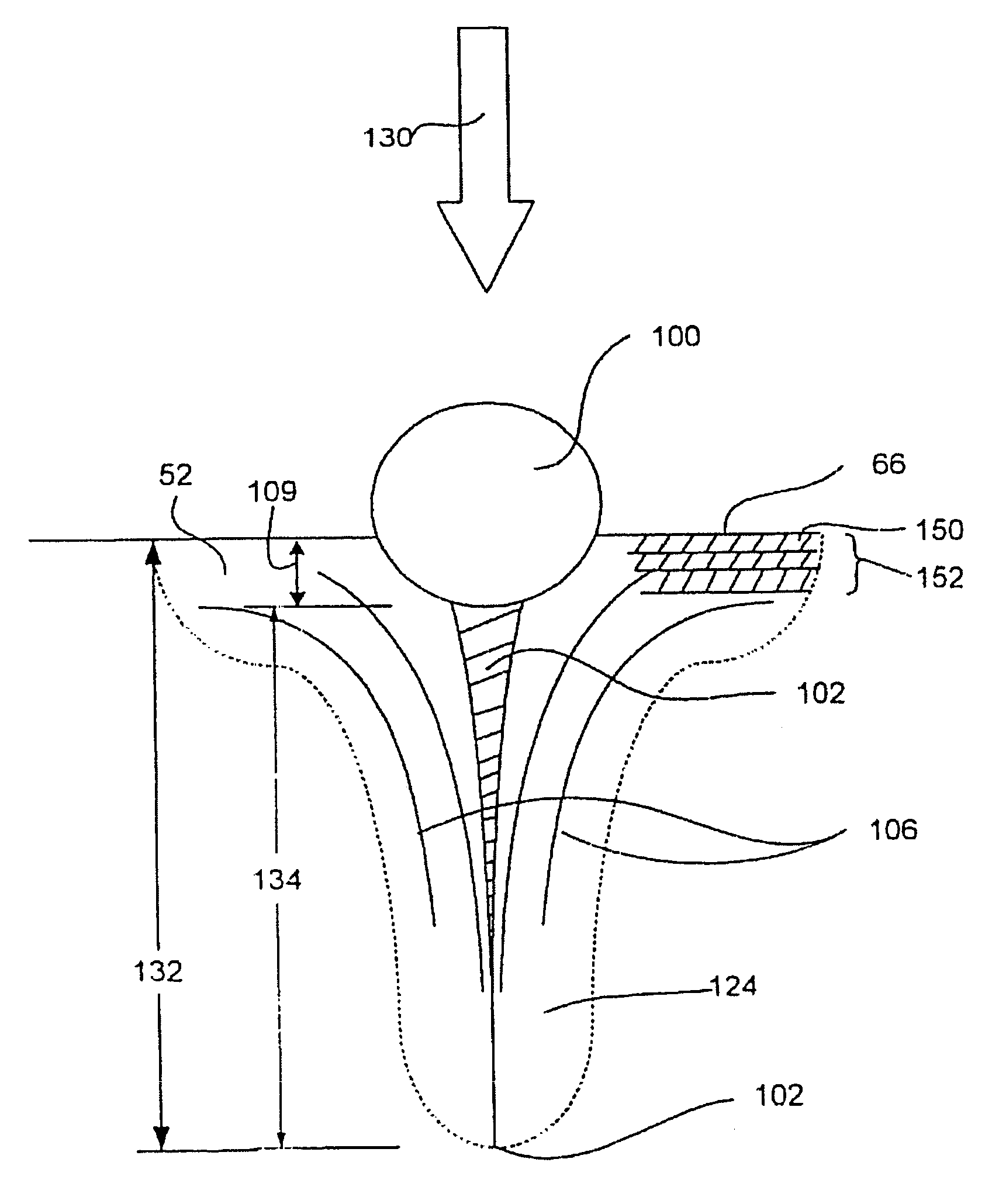
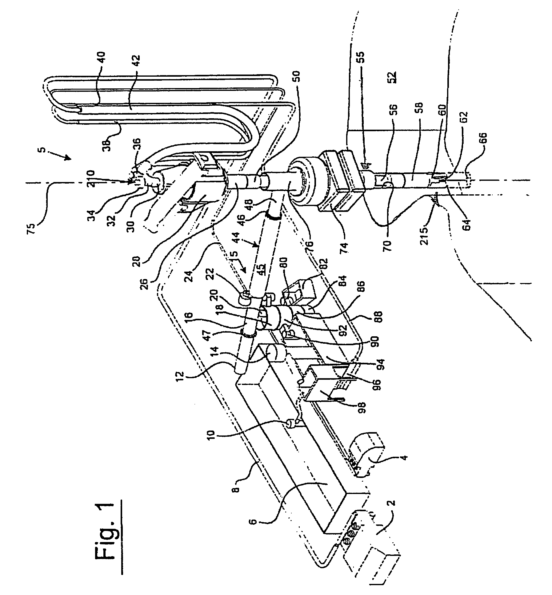
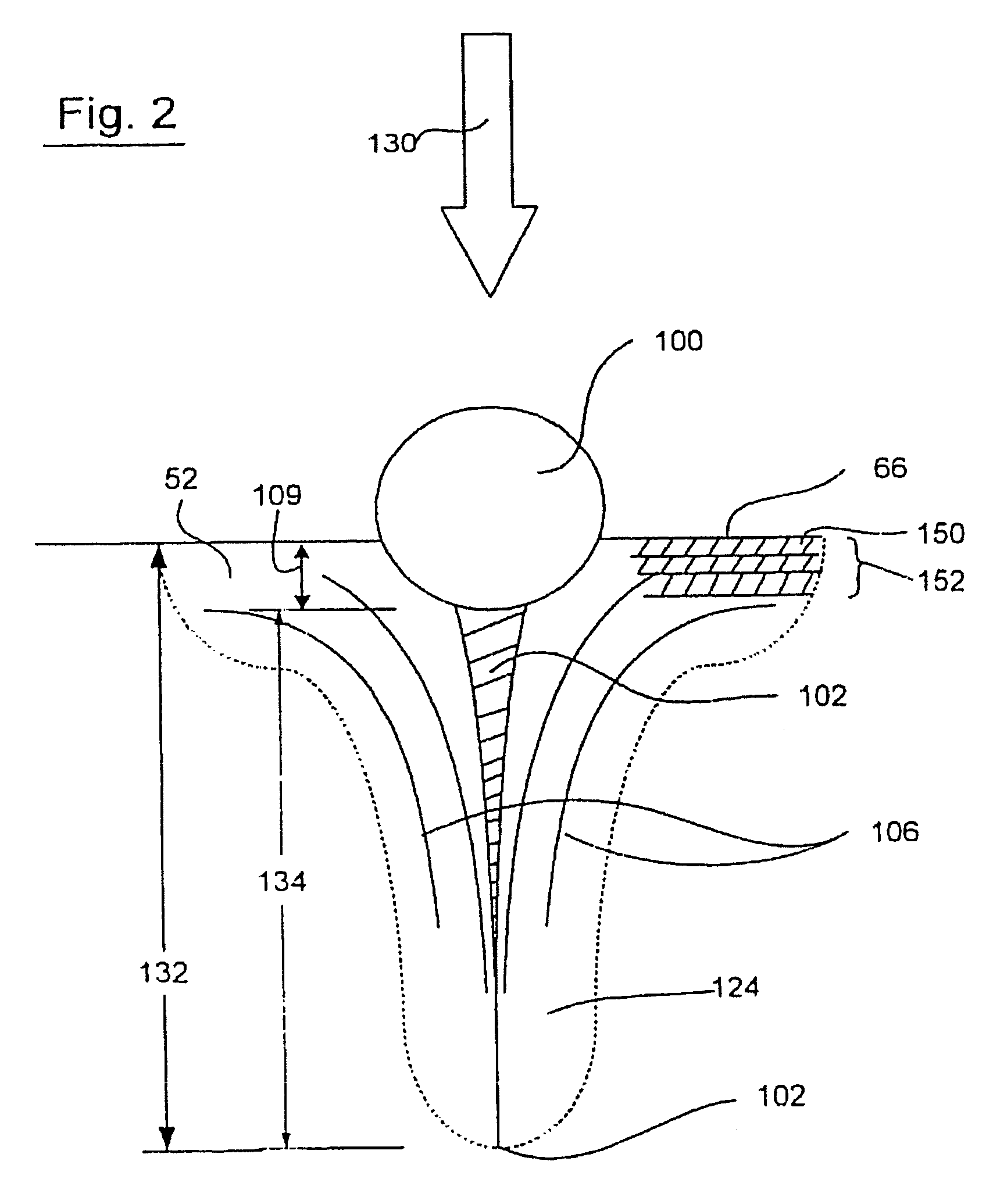
[0018]In the drawings and description that follows, like parts are marked throughout the specification and drawings with the same reference numerals, respectively. The drawing figures are not necessarily to scale. Certain features of the invention may be shown exaggerated in scale or in somewhat schematic form and some details of conventional elements may not be shown in the interest of clarity and conciseness. The present invention is susceptible to embodiments of different forms. Specific embodiments are described in detail and are shown in the drawings, with the understanding that the present disclosure is to be considered an exemplification of the principles of the invention, and is not intended to limit the invention to that illustrated and described herein. It is to be fully recognized that the different teachings of the embodiments discussed below may be employed separately or in any suitable combination to produce desired results. The various characteristics mentioned above,...


PUM


Abstract

A method and system for excavating a subterranean formation using a fluid comprising pumping the fluid through at least one nozzle such that a velocity of the fluid when exiting the nozzle is greater than a velocity of the fluid entering the nozzle. A plurality of solid material impactors are introduced into the fluid and circulated with the fluid through the nozzle. A substantial portion by weight of the solid material impactors has a mean diameter of equal to or less than approximately 0.100 inches. The fluid is pumped at a pressure level and a flow rate level sufficient to satisfy an impactor mass-velocity relationship wherein a substantial portion by weight of the solid material impactors has a minimum kinetic energy of approximately 0.075 Ft Lbs when exiting the nozzle. The substantial portion by weight of solid material impactors exit the nozzle and contact the formation.

Description

CROSS-REFERENCE TO RELATED APPLICATIONS[0001]This application is a continuation-in-part of U.S. patent application Ser. No. 10 / 825,338, filed Apr. 15, 2004, which claims priority to provisional application Ser. No. 60 / 463,903, filed Apr. 16, 2003, the disclosures of which are incorporated herein by reference.STATEMENT REGARDING FEDERALLY SPONSORED RESEARCH OR DEVELOPMENT[0002]Not Applicable.BACKGROUND[0003]The process of excavating a wellbore or cutting a formation to construct a tunnel and other subterranean earthen excavations is a very interdependent process that preferably integrates and considers many variables to ensure a usable bore is constructed. As is commonly known in the art, many variables have an interactive and cumulative effect of increasing drilling costs. These variables may include formation hardness, abrasiveness, pore pressures, and formation elastic properties. In drilling wellbores, formation hardness and a corresponding degree of drilling difficulty may incre...

Claims


Application Information

Patent Timeline
Patent Type & Authority Patents(United States)
IPC IPC(8): E21B43/114
CPCE21B7/18
Inventor TIBBITTS, GORDON
Owner PDTI HLDG
Why Eureka
Try Eureka