High precision power detector

a high-precision, power detector technology, applied in the direction of electric variable regulation, process and machine control, instruments, etc., can solve the problems of limiting the range of input amplitudes that can be accurately measured, reducing the bandwidth of input signals, and limiting the precision of power detectors

Inactive Publication Date: 2009-03-17
AVAGO TECH INT SALES PTE LTD
View PDF4 Cites 16 Cited by
  • Summary
  • Abstract
  • Description
  • Claims
  • Application Information

AI Technical Summary

Problems solved by technology

The precision of a power detector is limited by linearity errors and process and temperature variations.
This limits the range of input amplitudes that can be accurately measured to relatively high levels where the effects of temperature variation are less pronounced.
Further, input signal bandwidth decreases if low power input signals require increased amplification prior to detection.

Method used


Image

  • High precision power detector
  • High precision power detector
  • High precision power detector

Examples


Embodiment Construction

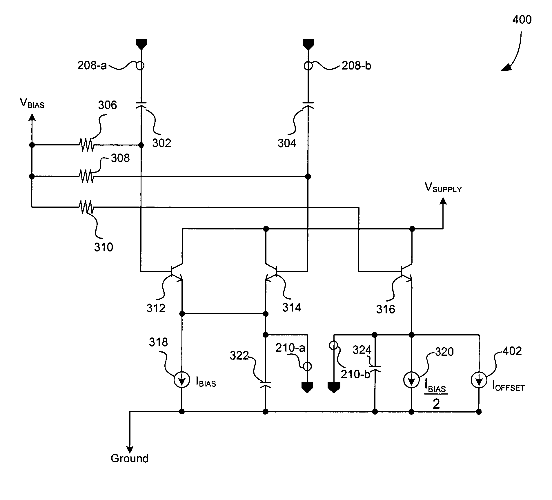
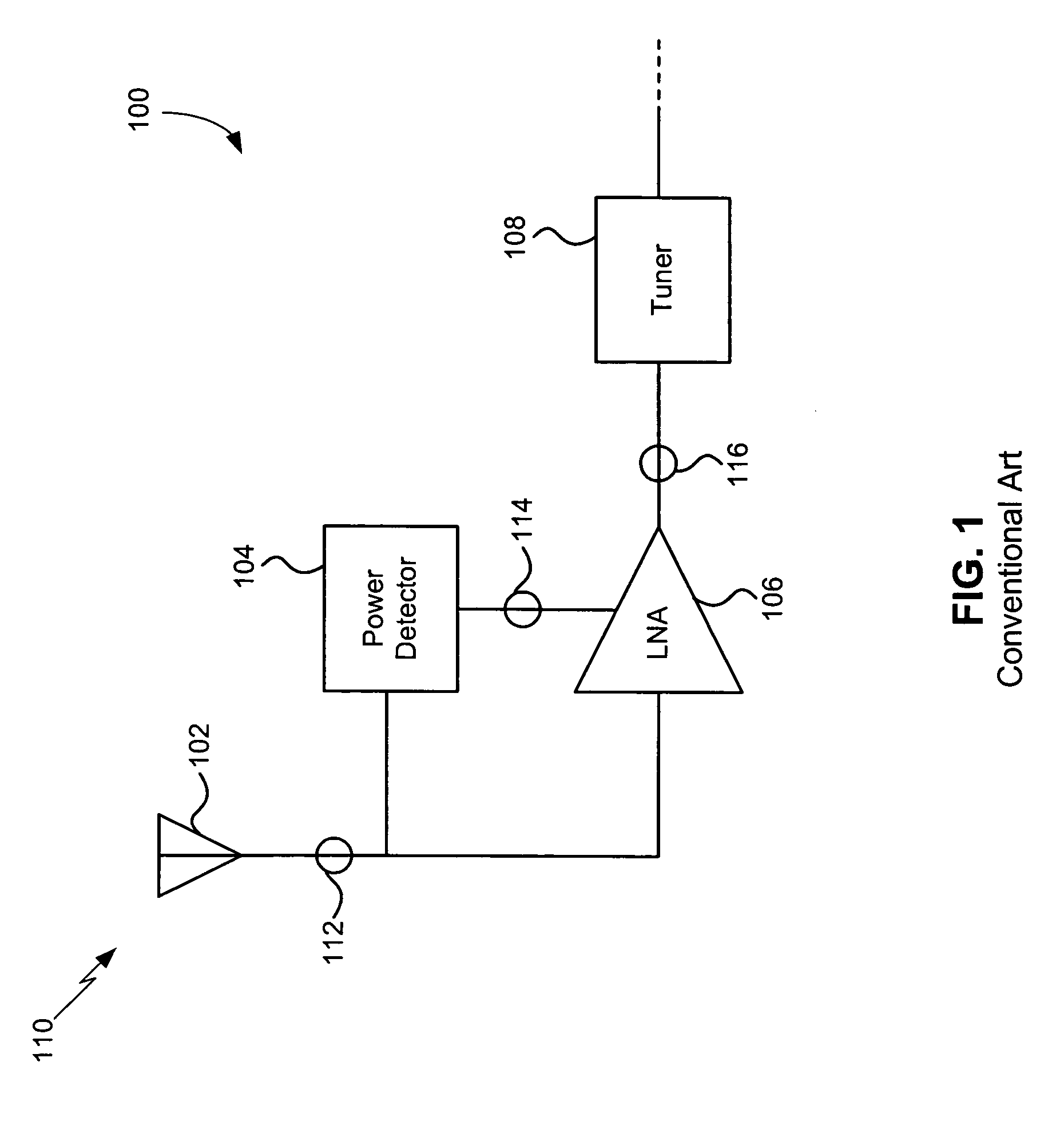
[0015]FIG. 1 illustrates the front-end of a conventional wireless receiver 100. The conventional wireless receiver 100 includes an antenna 102, a conventional power detector 104, a low noise amplifier (LNA) 106 and a tuner 108. The antenna 102 receives a transmitted wireless signal 110 and provides a received signal 112 to the conventional power detector 104 and the LNA 106. The LNA 106 amplifies the received signal 112 and provides an amplified received signal 116 to the tuner 108. The transmitted wireless signal 110 and the received signal 112 are typically radio frequency (RF) signals.

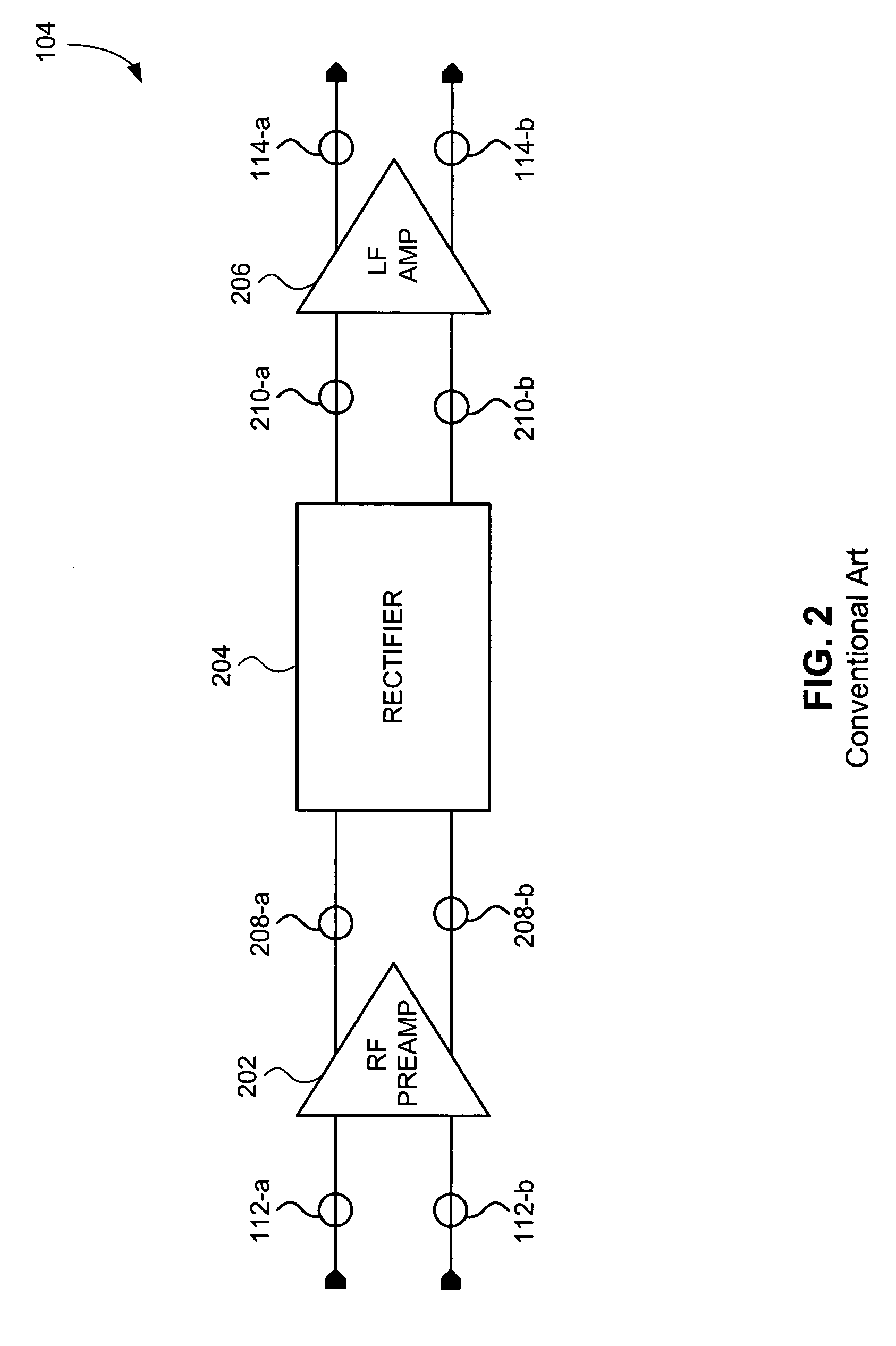
[0016]The tuner 108 operates optimally when the amplitude of the amplified received signal 116 is constant. The variable gain of the LNA 106 is adjusted to compensate for fluctuations in the amplitude of the received signal 112 to provide an amplified received signal 116 having constant amplitude. The variable gain of the LNA 106 is properly adjusted through the use of the conventional power detecto...


PUM


Abstract

A power detector having temperature compensation for improved measurement performance includes a pair of rectifier transistors coupled to a differential input signal biased by a first temperature dependent current. An output of the pair of rectifier transistors provides a first component of a differential DC output signal. The first component of the differential DC output signal includes a DC voltage proportional to an amplitude of the differential input signal plus an offset voltage. The power detector further includes a reference transistor biased by a reference current. The reference current includes a second temperature dependent current and a temperature independent offset current for temperature compensation. An output of the reference transistor provides a second component of the differential DC output signal that includes a reference voltage. The temperature independent offset current is adjusted such that the reference voltage substantially equals the offset voltage, thereby improving the precision of the power detector.

Description

CROSS REFERENCE TO RELATED APPLICATIONS[0001]This application claims the benefit of U.S. Provisional Patent Application No. 60 / 635,175, filed Dec. 13, 2004, which is incorporated herein by reference in its entirety.BACKGROUND OF THE INVENTION[0002]1. Field of the Invention[0003]The present invention generally relates to power detectors. More specifically, the present invention provides a power detector having temperature compensation for improved measurement performance.[0004]2. Background Art[0005]Power detectors measure the amplitude or power of an input signal. The precision of a power detector is limited by linearity errors and process and temperature variations. The constituent components of a power detector typically exhibit a strong dependence on temperature, especially at low input power levels. Therefore, as temperature varies, the output measurement provided by a power detector can fluctuate considerably for a given constant input amplitude. This limits the range of input ...

Claims


Application Information

Patent Timeline
Patent Type & Authority Patents(United States)
IPC IPC(8): G05F3/04G05F3/16
CPCH03D1/18Y10S323/907
Inventor MANSTRETTA, DANILO
Owner AVAGO TECH INT SALES PTE LTD
Why Eureka
Try Eureka