Semiconductor physical quantity sensor and method for manufacturing the same
a technology of magnetic field and sensor, which is applied in the direction of turn-sensitive devices, capacitors with electrode area variation, instruments, etc., can solve the problems of reducing the production field, affecting affecting the normal movement of the movable electrode, so as to improve the manufacturing yield of the sensor, increase the thickness of the insulation film, and increase the distance between the movable electrode and the substrate.
- Summary
- Abstract
- Description
- Claims
- Application Information
AI Technical Summary
Benefits of technology
Problems solved by technology
Method used
Image
Examples
first embodiment
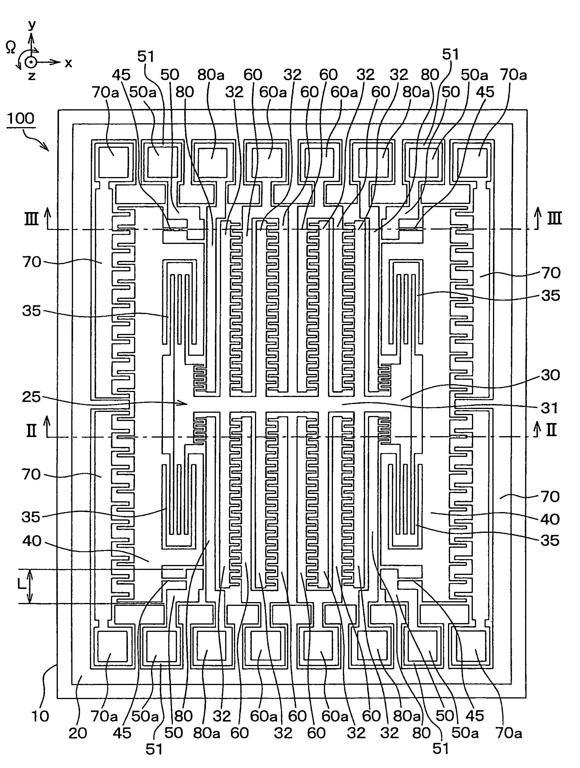
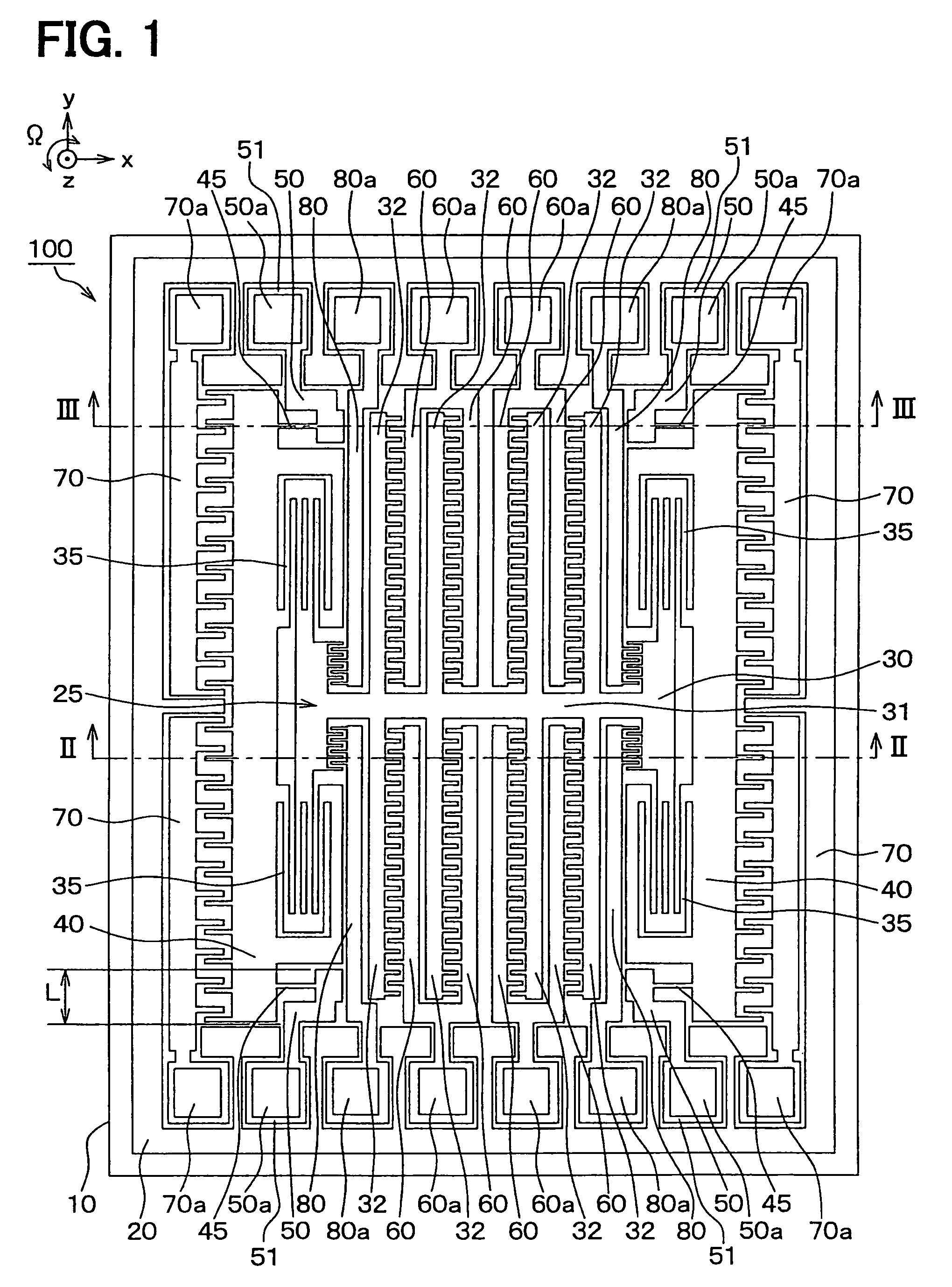
[0046]A capacitance type semiconductor physical quantity sensor according to a first embodiment of the present invention is applied to a capacitance type angular rate sensor.
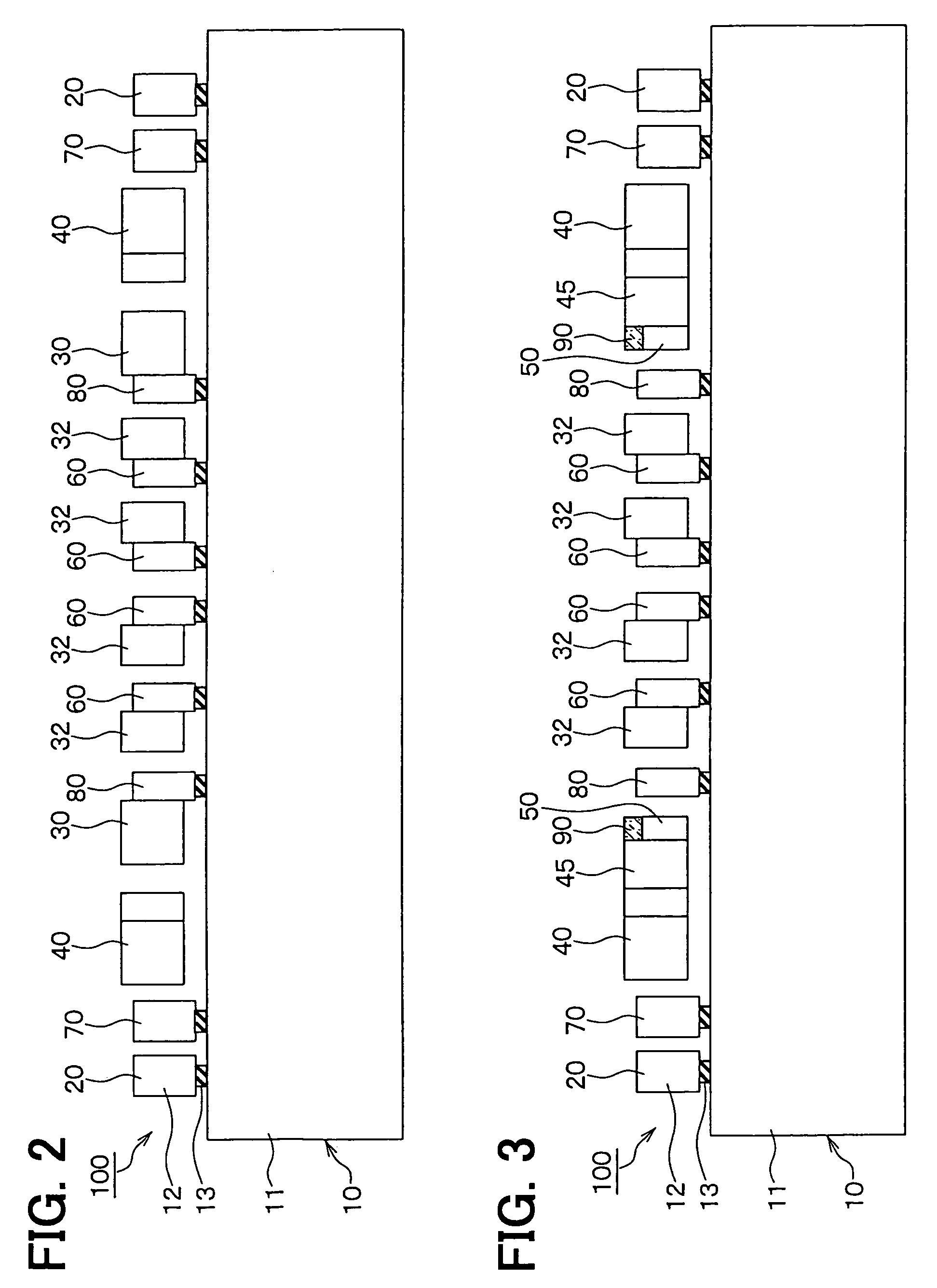
[0047]FIG. 1 is a plan view for schematically showing a capacitance type angular rate sensor 100 according to the first embodiment. Also, FIG. 2 is a sectional view for schematically indicating the capacitance type angular rate sensor 100, taken along a line II-II of FIG. 1. FIG. 3 is a sectional view for schematically showing the angular rate sensor 100, taken along a line III-III of FIG. 1.
[0048][Structure]
[0049]This angular rate sensor 100 is made of a semiconductor substrate 10 such as a silicon substrate. Since trenches are formed in this semiconductor substrate 10 by employing the well-known semiconductor manufacturing technique such as an etching process, as indicated in FIG. 1, a frame unit 20 is segmented to be formed in an outer peripheral unit of this semiconductor substrate 10 and also, a movable ele...
second embodiment
[0158]FIG. 9 is a diagram for schematically showing a sectional structure of a capacitance type angular rate sensor 200 according to a second embodiment of the present invention.
[0159]A plane structure of the angular rate sensor 200 is made similar to the plane structure shown in FIG. 1. FIG. 9 represents the angular rate sensor 200 by way of the sectional view shown in FIG. 2, namely, such a sectional view corresponding to the sectional view taken along the line II-II in FIG. 1.
[0160]In the angular rate sensor 100 shown in FIG. 1 to FIG. 3, the substantially entire portions of the fixed electrodes 60, 70, 80 are supported via the embedded oxide film 13 by the silicon substrate 11 to be fixed thereon (refer to FIG. 2 and FIG. 3).
[0161]To the contrary, in the angular rate sensor 200, the fixed electrodes 60 to 80 are supported via the embedded oxide film 13 at respective portions which are located in the peripheral unit of the silicon substrate 11, at portions where the pads 60a to 8...
third embodiment
[0169]FIG. 10 is a diagram for schematically showing a sectional structure of a capacitance type angular rate sensor 300 according to a third embodiment of the present invention.
[0170]A plane structure of the angular rate sensor 300 is made similar to the plane structure shown in FIG. 1. FIG. 10 represents the angular rate sensor 300 mode by way of the sectional view shown in FIG. 2, namely, such a sectional view corresponding to the sectional view taken along the line II-II in FIG. 1.
[0171]Similar to the angular rate sensor 200 shown in FIG. 9, in the angular rate sensor 300, the fixed electrodes 60 to 80 are supported via the embedded oxide film 13 at respective portions which are located in the peripheral unit of the silicon substrate 11, at portions where the pads 60a to 80a are formed under cantilever conditions.
[0172]This angular rate sensor 300 is featured by that the fixed electrodes 60 to 80 are coupled under such a condition that these fixed electrodes 60 to 80 are support...
PUM
 Abstract
Description
Claims
Application Information
 - R&D
- Intellectual Property
- Life Sciences
- Materials
- Tech Scout
- Unparalleled Data Quality
- Higher Quality Content
- 60% Fewer Hallucinations
Browse by: Latest US Patents, China's latest patents, Technical Efficacy Thesaurus, Application Domain, Technology Topic, Popular Technical Reports.
© 2025 PatSnap. All rights reserved.Legal|Privacy policy|Modern Slavery Act Transparency Statement|Sitemap|About US| Contact US: help@patsnap.com


