
Store ejection system utilizing a mixed fuel and oxidizer in a power source

a technology of ejection system and power source, which is applied in the direction of launching weapons, machines/engines, transportation and packaging, etc., can solve the problems of safety hazards, increased cost and down time, and air flow on the underside of the aircraft that may interfere with the smooth drop of the store, so as to simplify the design of the power source and the ejector. , the effect of non-corrosive natur

Inactive Publication Date: 2009-03-24
RAYTHEON CO
View PDF30 Cites 7 Cited by
  • Summary
  • Abstract
  • Description
  • Claims
  • Application Information

AI Technical Summary

Benefits of technology

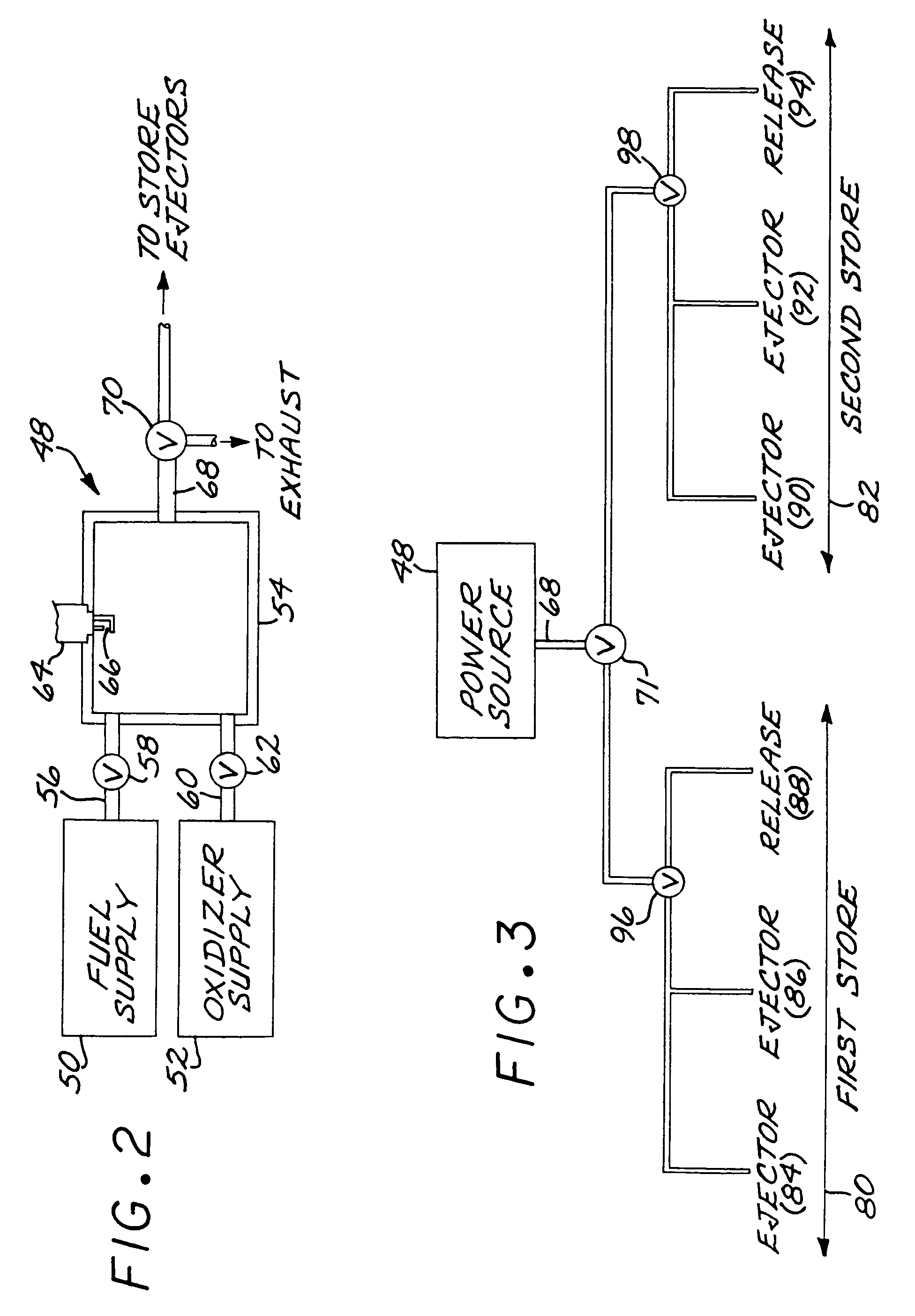
[0009]The present approach provides a store ejection system including a power source that produces the required ejection force controllably and rapidly. The power source is light in weight and compact, and does not adversely affect the aerodynamics of the aircraft. It is safe to use. The combustion product gas is desirably a mixture of carbon dioxide and water, which is non-corrosive and does not damage either the power source or the ejector. The power source has a short recycle time that permits stores to be ejected in rapid sequence and allows the store ejector to be used to free hung stores. It may be used to power one or multiple ejectors, for one or multiple stores. The number of ejections is limited only by the amounts of fuel and oxidizer available, which may be selected according to the number of stores to be deployed.
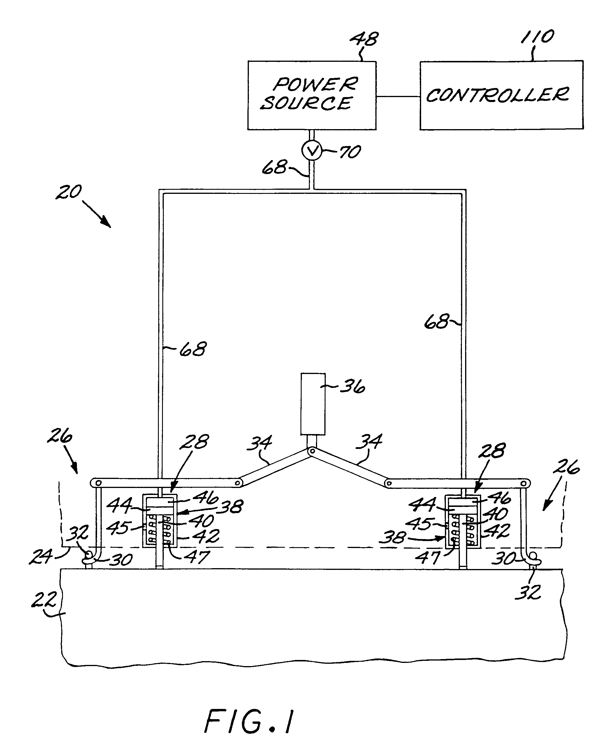
[0012]The store ejection system further comprises a store ejector including a release mechanism that causes the hooks to rotate, and may include a piston to assist in pushing the store away from the aircraft. When there is no piston present, the power source provides high-pressure gas that forces the combustion chamber to move. That impact forces the linkage system to travel and rotate both hooks. Once the hooks are released, the store falls away from the aircraft. There is a sufficient gap at the end of the gas chamber to allow the expanding gas to dissipate in the air, relieving the pressure within the chamber.
[0013]If there is a piston present, not only does the high-pressure gas force the linkage system to rotate both hooks, but it also forces the piston to expand along the cylinder in which it resides. The piston helps to push the store away from the aircraft after the hooks are released. When the piston is fully expanded, gas release holes are exposed, allowing gas to escape to the atmosphere. The power source may be used to power several ejection systems at any one time. The fuel line ideally feeds several ejection systems. A regulator valve on each system prevents the fuel from igniting within the line or from accidentally igniting the other ejector systems.
[0015]The store-ejector power source of the present approach is based upon a controllable combustion of the fuel and the oxidizer in a combustion chamber that generates a pressurized gas to power the ejector. The fuel and oxidizer are safe and reliable to use. The gaseous combustion product is non-toxic and non-corrosive. The non-corrosive nature of the combustion product simplifies the design of the power source and the ejector. Key benefit are that the power source may be used for multiple stores, and may be rapidly recycled to permit rapid sequential ejection of the multiple stores.

Problems solved by technology

For more modern, faster aircraft, the air flow on the underside of the aircraft may interfere with the smooth, controllable dropping of the store away from the aircraft after it is released.
One drawback is that each power source allows for only one release or ejection.
This inability to utilize the power source for multiple ejections not only creases added cost and down time, but it is also a safety hazard.
Occasionally, stores become caught or “hung” on the hooks after the power source has been used.
This becomes a risk because of the lack of control over when or where the store is released.
In addition, the combustion product of the pyrotechnic device does not burn cleanly, resulting in an extremely corrosive, sticky by-product.
While these pyrotechnic devices are generally reliable, there is still the risk of unintentional detonations.
There have been occasions when a static electrical discharge from clothing was sufficient to set off the device before it could be loaded into the ejector, resulting in an injury.
A number of other power sources for ejection mechanisms have been proposed, but most are relatively complex or require too much space to be utilized effectively.
These other power sources are also too heavy for many applications, and also may affect the aerodynamics of the aircraft.

Method used


Image

  • Store ejection system utilizing a mixed fuel and oxidizer in a power source
  • Store ejection system utilizing a mixed fuel and oxidizer in a power source
  • Store ejection system utilizing a mixed fuel and oxidizer in a power source

Examples


Embodiment Construction

[0020]FIG. 1 depicts the relevant functional elements of a store ejection system 20. A store 22, such as a bomb, a fuel tank, or a reconnaissance pod, is supported below an aircraft 24, as from its fuselage or a wing-mounted bomb rack. The store ejection system 20 includes two main subsystems. The store 22 is supported on a store release mechanism 26, and after release is forced away from the aircraft 24 by a store-ejector subsystem 28.

[0021]The store release mechanism 26 includes a pair of suspension hooks 30 extending downwardly from the aircraft 24 and engaging a respective pair of lugs 32 extending upwardly from the store 22 to retain the store 22 supported from the aircraft 24. A mechanical linkage 34 within the aircraft 24 extends to each of the suspension hooks 30 and either holds them in position to engage the respective lugs 32 (the illustrated position), or, upon activation of the linkage 34 by a release activator 36, pivots the hooks 30 so that they no longer engage the l...


PUM


Abstract

A store ejection system for an aircraft includes a store ejector, and a power source for the store ejector. The power source has a fuel supply of a flowable combustible fuel, an oxidizer supply of a flowable oxidizer, a combustion chamber that controllably receives the combustible fuel from the fuel supply and the oxidizer from the oxidizer supply and forms a combustible mixture thereof, an igniter that controllably ignites the combustible mixture in the combustion chamber, and a combustion-gas line extending from the power source to the store ejector.

Description

[0001]This invention relates to store ejection systems for deployable stores, such as bombs, fuel tanks, and reconnaissance pods, on an aircraft.BACKGROUND OF THE INVENTION[0002]An external deployable store, such as a bomb, is usually supported below an aircraft with an ejection system. The ejection system includes a pair of suspension hooks that engage the lugs on the top side of the store. When the store is to be released, the suspension hooks are operated to disengage the lugs so that the store may fall away from the aircraft. The suspension hooks are usually released by the firing of a pyrotechnic device activated by an electrical current. The resulting gases formed by the explosion of the pyrotechnic device create enough force to rotate the hooks free of the lugs and release the store.[0003]The use of only a hook-and-lug arrangement was workable for some of the early types of slowly flying aircraft. The force of gravity was sufficient to allow the store to fall away from the ai...

Claims


Application Information

Patent Timeline
IPC IPC(8): B64D1/04F02C3/20
CPCB64D1/04
Inventor BURNETT, LAURA MARIEBAILEY, ROBERT ALANKILLIAN, ROBERT JAMES
Owner RAYTHEON CO
Learn More