Safety tire including composite sheet with confined flexibility

a composite sheet and flexible technology, applied in the field of composite sheet and pneumatic tires, can solve the problems of low bending stiffness, low tensile modulus, and small compression load, and achieve the effect of reducing the risk of slipping

Inactive Publication Date: 2009-03-24
SU LIFENG +1
View PDF23 Cites 3 Cited by
  • Summary
  • Abstract
  • Description
  • Claims
  • Application Information

AI Technical Summary

Benefits of technology

[0036]When composite sheet deforms within predetermined ranges, said stiff objects usually only make substantially rigid movement, and the rubber material deforms substantially to accommodate the shape change of composite sheet. As a result, composite sheet has good flexibility within said predetermined ranges of structure movements and is capable of achieving substantially smooth curvature of desirable shape just like ply sheet. When composite sheet deforms beyond said predetermined ranges, stiff objects start entering into locking position and the resistance to further structure movement, which is mainly contributed from stiff objects, increases significantly, and therefore, further structure movement is prevented. When cords present in present invention, they are usually covered by said stiff objects, and therefore, are shielded from direct contact with pointy or sharp edge external object. Said stiff object usually has large external surface through which moderate forces may be passed between stiff object and surrounding rubber at low to moderate stress level. When said stiff object is forced to contact with its adjacent stiff objects or the optional cords, large forces may be passed between them with very small strain increments. Said rubber material, which is filled in the gaps between adjacent stiff objects, has very low modulus and is capable of bearing large deformation. The aforementioned features of rubber keep the integrity of the whole structure and provide the flexibility to the structure before stiff objects enter into locking position. It is preferable to pre-treat the stiff object with coating or chemicals to increase its bond with rubber.
[0061]Other advantages of present invention include: making a tire that has substantially higher lateral spring coefficient and rotational stiffness which provide vehicle good response to steering, accelerating and breaking; making a tire which has very small reduction of section height when it lost inflation pressure, so that said tire can be used to replace solid tire; making heavy tire with reduced thickness of sidewall but higher bending stiffness; making a tire which has significantly lower operational inflation pressure to achieve superior performance for some special needs, like higher road tracking, special air-dynamic characteristics; make a tire or pipe with extremely high burst pressure.

Problems solved by technology

Ply sheet has high tensile modulus along its cord direction but low bending stiffness and, it can only bear small compression load.
When inflation pressure is lost for some reason, the structure becomes unstable and the working load has to be passed to adjacent structure.
Among other drawbacks of this type of structure are puncture / cut prone and low compression load bearing ability.
As a result, the ride comfort and heat buildup inside tire and deterioration in dynamic tire performance under normal condition become trade-offs in this type of tire.
As a result, the tire handling ability becomes hard to predict under flat tire condition, especially when vehicle is cornering.
The third type of run-flat tire is almost impractical.
It is hard to find any metallic material to make a ring which can tolerate such cyclic large deformation which tire has experienced at normal working condition.
Further more, this type of tire is unstable under flat tire condition since flexible tire structure is not capable of transferring the load between rings and rim under this condition.
However, the increment of bending stiffness of cord is undesirable in some engineering applications.
Further more, the improvement of puncture resistance of the ply structure in those patented inventions is not sufficient to prevent the failure of the structure in most cases.

Method used


Image

  • Safety tire including composite sheet with confined flexibility
  • Safety tire including composite sheet with confined flexibility
  • Safety tire including composite sheet with confined flexibility

Examples


Embodiment Construction

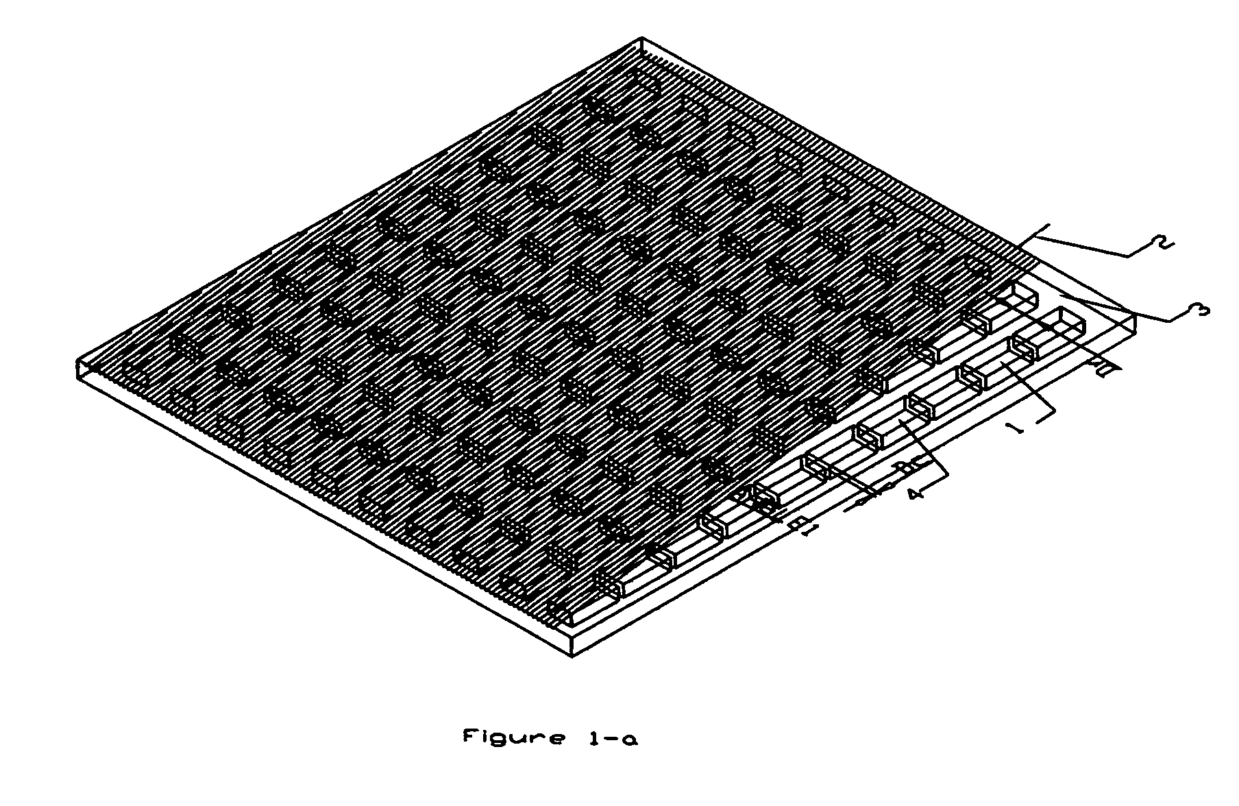
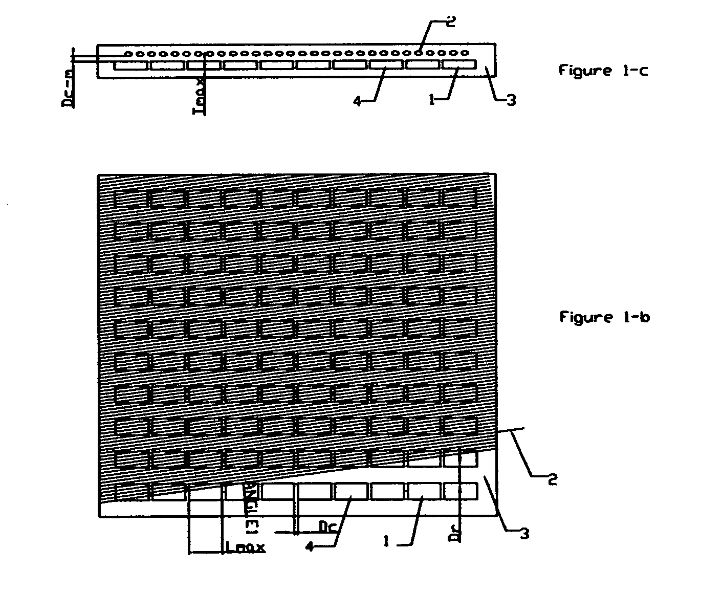
[0078]In FIG. 1-a, 1 is stiff object, 2 is cord which is optionally presented in composite sheet, 3 is rubber material, 4 represents the bounding box of stiff object 1. In FIGS. 1-a, 1-b and 1-c, the details of the shape of stiff object 1 are ignored and, stiff object is represented by its bounding box 4 to indicate the position in composite sheet. Stiff objects may have any shapes and each piece may or may not be the same size. FIG. 2a, 2b, 2c, 2d are some embodiments of the shapes of stiff objects. The bounding box (4) of stiff object describes the maximum dimensions of stiff object along three major directions (thickness direction, row direction and column direction). Each bounding box has a distance Dr to its adjacent bounding box in same row and has a distance Dc to its adjacent bounding box in same column. To different stiff object, the value of Dr (and / or Dc) may or may not be the same. The values of Dr and Dc may be positive, or, negative. The negative value means that the s...


PUM


Abstract

A composite sheet has confined flexibility and is used in a safety pneumatic tire which is self-supporting under zero inflation pressure. The composite sheet comprises a matrix of high modulus solid objects, low modulus material, and optionally a matrix of cords, the high modulus solid objects being assembled to form a mechanism which allows the composite sheet to bend easily within predetermined ranges and confines the composite sheet from further bending when the limits of the predetermined ranges are reached. The safety pneumatic tire comprises a pair of the composite sheets disposed at sidewall regions under a carcass and / or a layer of the composite sheet disposed above a belt package. A method of making the composite sheet includes forming a chain of the high modulus solid objects having a desired locking position.

Description

CROSS-REFERENCE TO RELATED APPLICATIONS[0001]This application claims the benefit of PPA Ser. No. 60 / 477,072, filed 2003 Jun. 9 by the present inventors.FEDERALLY SPONSORED RESEARCH[0002]Not ApplicableSEQUENCE LISTING OR PROGRAM[0003]Not ApplicableDEFINITION OF TERMINOLOGY[0004]1. “locking position of stiff object”: when a group of external forces apply to two immediately adjacent stiff objects, the two objects can relatively move easily until they are positioned in such a way that further movement cause significant increment of stress inside their bodies. And, therefore, the high resistance to further body movements starts being mobilized from two stiff objects. This extreme position is called the locking position of the two stiff objects to this group of external forces. Different group of external forces will generate different form of relative movements of the two stiff objects. As a result, different group of external forces has its own locking position to the same pair of stiff...

Claims


Application Information

Patent Timeline
Patent Type & Authority Patents(United States)
IPC IPC(8): B60C17/00B60C13/00B60C19/12B60C9/02B60C9/18B60C9/20B60C15/06
CPCB60C9/02B60C9/18B60C9/20B60C15/06B60C17/0009B60C9/0207Y10T152/1018Y10T428/24876Y10T152/10864Y10T152/10216Y10T152/10828Y10T428/249924B60C9/11
Inventor SU, LIFENGGAO, QI
Owner SU LIFENG
Why Eureka
Try Eureka