Transmission mechanism for electrical nail gun

a transmission mechanism and nail gun technology, applied in the direction of nailing tools, stapling tools, manufacturing tools, etc., can solve the problems of affecting safety and stability, affecting the structure affecting the efficiency of the clutch assembly, so as to save the space of the solenoid and simplify the clutch assembly

Inactive Publication Date: 2009-03-24
DE POAN PNEUMATIC
View PDF21 Cites 25 Cited by
  • Summary
  • Abstract
  • Description
  • Claims
  • Application Information

AI Technical Summary

Benefits of technology

[0007]What is needed, therefore, is to provide a transmission mechanism configured for an electrical nail gun, which simplify a clutch assembly in a previous technology, save space for a solenoid, and overcome not to generate a component force not along stroke nail direction during long-term use of the nail gun.
[0017]Furthermore, the driving wheel is substantially a gear wheel, and the linear transmission unit includes a rack in mesh with the gear wheel to helpfully transform the rotary kinetic energy of the driving wheel into the linear kinetic energy of the linear transmission unit.
[0018]It is a novelty for employing magnetic field effect of the solenoid to control engagement or disengagement of the driving wheel in / from the flywheel and for a transmission method of kinetic energy. Because the solenoid is received in the cylinder adjacent to the flywheel, and the two opposite end surfaces of the cylinder and the driving wheel constitute the clutch, the configuration space of the components is sufficiently saved. Moreover, the rotary kinetic energy of the flywheel is fully transmitted to the driving wheel due to the two opposite end surfaces of the driving wheel and the cylinder. In greater detail, the gear wheel is used as the driving wheel and the rack is used as the follower component of the linear transmission unit. Thus, it may be a advantageous to transform the rotary kinetic energy of the gear wheel into the linear kinetic energy of the rack, thereby improving durability of the transmission mechanism for the electrical nail gun even if the gear wheel and the rack is worn in long-termed use.

Problems solved by technology

However, the structure of the clutch assembly is complicated due to too many components.
The solenoid is disposed in the housing away from the flywheel, therefore, it is a disadvantage to save configuration room.
However, during a long-term use, an abrasion may be produced by friction between the roller, the driving stand, and the flywheel to thereby broaden mesh clearance.
When the driving stand of the stroke bar is pushed by the roller towards the flywheel to mesh with the flywheel, a component acting force is produced not along a direction of impacting the nail due to clearance, thereby affecting safety and stability as the driving stand is driving the stroke bar to impact the nail.
Furthermore, the solenoid is disposed in the housing away from the flywheel or the clutch assembly; therefore, it is a disadvantage to save configuration room.

Method used


Image

  • Transmission mechanism for electrical nail gun
  • Transmission mechanism for electrical nail gun
  • Transmission mechanism for electrical nail gun

Examples


Embodiment Construction

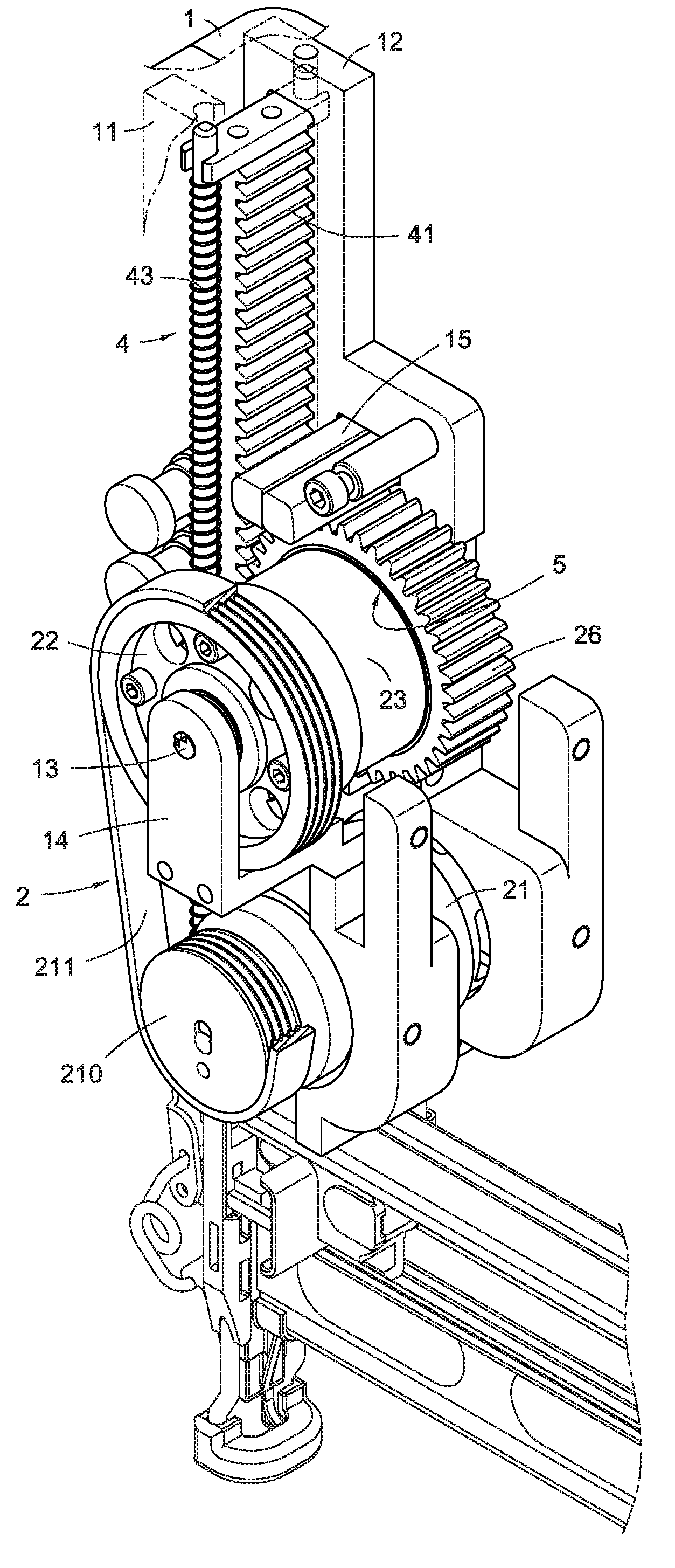
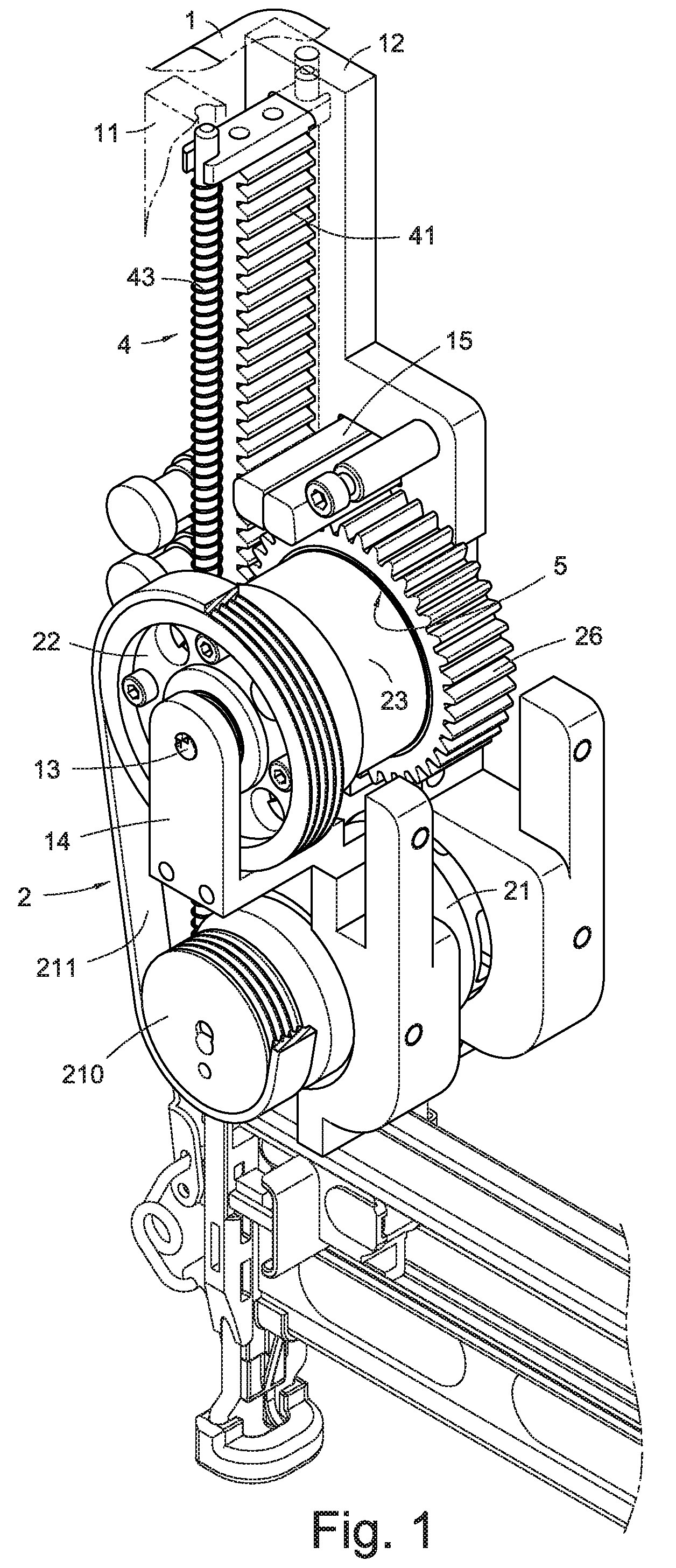
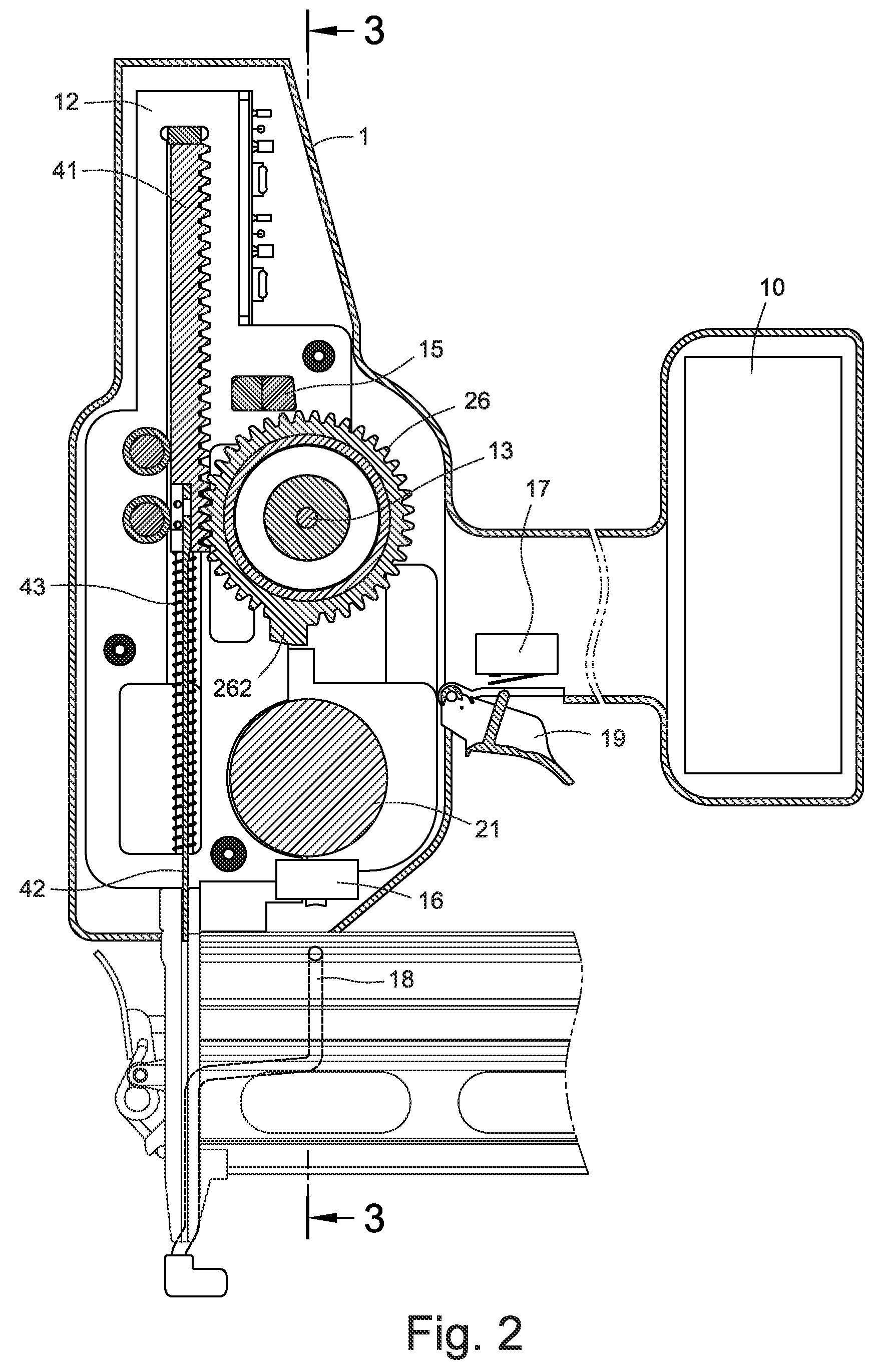
[0029]Referring to FIGS. 1 to 3, a transmission mechanism for an electrical nail gun in accordance with a first embodiment of the present invention is shown. A suitable power source, such as a battery pack 10 for providing direct current to the transmission mechanism, is received in a distal end of a housing 1. Two opposing supporting bracket 11, 12 are formed on a head portion of the housing 1 to mount a rotary transmission unit 2 and a linear transmission unit 4 thereon. A first switch 16 and a second switch 17 are formed on the housing 1. The first switch 16 is disposed on a bottom end of the housing 1 for a safe sliding rod 18 being capable of touching the first switch 16. The second switch 17 is located on an end side of the housing 1 where a trigger 19 mounted on the housing 1 can touch the second switch 17.

[0030]The rotary transmission unit 2 includes a motor 21, a flywheel 22, a solenoid 24, and a moveable driving wheel 26.

[0031]The motor 21, which is securely mounted on bot...


PUM


Abstract

A transmission mechanism for an electrical nail gun includes a rotary transmission unit and a linear transmission unit in a housing of the electrical nail gun. The rotary transmission unit includes a motor driven by electricity, a flywheel driven by the motor and extending to form a cylinder thereon, a solenoid activated by electricity, and a moveable driving wheel adjacent to an end side of the cylinder. A clutch is formed between the cylinder and the driving wheel. The solenoid is buried in the cylinder so that a magnetic conductivity loop is constructed around the solenoid to produce the magnetic field when the solenoid is activated. The driving wheel is attracted to move to an engagement position to be driven by the flywheel, thereby driving the linear transmission unit to impact a nail when the solenoid is activated by electricity, and the driving wheel returns to a disengagement position to disengage from the flywheel, thereby stopping driving the linear transmission unit when the solenoid is demagnetized.

Description

BACKGROUND OF THE INVENTION[0001]1. Field of the Invention[0002]The present invention relates to a transmission mechanism for an electrical nail gun, and more particularly to a transmission mechanism in which a solenoid is received in a cylinder of a flywheel, a clutch is located between the cylinder and an end side of a driving wheel, a magnetic field is produced by activating the solenoid to control engagement or disengagement of the driving wheel to transmit kinetic energy of the rotary flywheel.[0003]2. Description of Related Art[0004]An electrical nail gun is a type of tool used to drive nails into wood or some other kind of material. Usually, there is a battery pack or an AC electrical power source in a housing of the electrical nail gun to provide electrical power to a motor, thereby rotating the motor. A rotary kinetic energy of the motor is transformed into a linear kinetic energy by a transmission mechanism to drive a strike bar to impact nails.[0005]Among a more advanced ...

Claims


Application Information

Patent Timeline
Patent Type & Authority Patents(United States)
IPC IPC(8): B25C5/15
CPCB25C1/06
Inventor LIANG, CHIA-SHENGCHANG, CHIN-LUNGTSENG, CHU-HSIANG
Owner DE POAN PNEUMATIC
Why Eureka
Try Eureka