Injection valve with a corrosion-inhibiting, wear-resistant coating and method for the production thereof

a technology of injection valve and coating, which is applied in the direction of spray nozzles, machines/engines, mechanical equipment, etc., can solve the problems of high reliability and particularly long service life, and achieve the effects of less force, less corrosion, and increased sealing seat tightness

Inactive Publication Date: 2009-03-24
ROBERT BOSCH GMBH
View PDF22 Cites 15 Cited by
  • Summary
  • Abstract
  • Description
  • Claims
  • Application Information

AI Technical Summary

Benefits of technology

[0008]In contrast, the fuel injector according to the present invention has several advantages over the related art. For instance, the surfaces in contact with water, which are provided with a corrosion-inhibiting or friction-reducing coating, are protected from chemical or mechanical corrosion, in particular chemical corrosion and frictional wear, in an effective and long-lasting manner.
[0011]If the joints, in particular the welded seams that are in contact with the water, are advantageously coated by the corrosion-inhibiting or friction-reducing layer, this will also contribute to a longer service life and improved reliability of the fuel injector. Coating the guide and gliding surfaces of the fuel injector that come into contact with water results in a particularly long service life and high reliability as well.
[0013]It is possible to increase the tightness of the sealing seat without having to revert to smaller and more cost-intensive manufacturing tolerances. Because of the elastic sealing ring, the components disposed in the sealing seat or in operative connection therewith are subjected to less force. This increases the service life and reliability of the fuel injector. It is particularly advantageous to use a sealing ring here that is at least partially made of an elastomeric material.
[0014]The method according to the present invention has the advantage of allowing the simple and thus cost-effective manufacture of a fuel injector by which the mentioned advantages may be achieved.
[0015]Since the components are joined by welding or soldering, especially cost-effective and reliable joints are obtained. It is particularly advantageous if the material forming the corrosion-inhibiting or friction-reducing coating is fed to the location to be coated by means of a canula. In this way, the apportioning may be implemented with particular precision, in a material-saving and thus cost-effective manner.
[0016]The aftertreatment in the form of a centrifugation of the joined components provides for an especially complete coating, since in particular the material forming the coating is then able to penetrate the tiniest gaps, for instance of the welded joint. Due to the thermal treatment the corrosion-inhibiting or friction-reducing layer is joined to the particular surface in an especially effective and durable manner.

Problems solved by technology

Coating the guide and gliding surfaces of the fuel injector that come into contact with water results in a particularly long service life and high reliability as well.

Method used


Image

  • Injection valve with a corrosion-inhibiting, wear-resistant coating and method for the production thereof
  • Injection valve with a corrosion-inhibiting, wear-resistant coating and method for the production thereof
  • Injection valve with a corrosion-inhibiting, wear-resistant coating and method for the production thereof

Examples


Embodiment Construction

[0021]In the following, exemplary embodiments of the present invention are described by way of example. Identical parts have been provided with matching reference numerals in all of the figures.

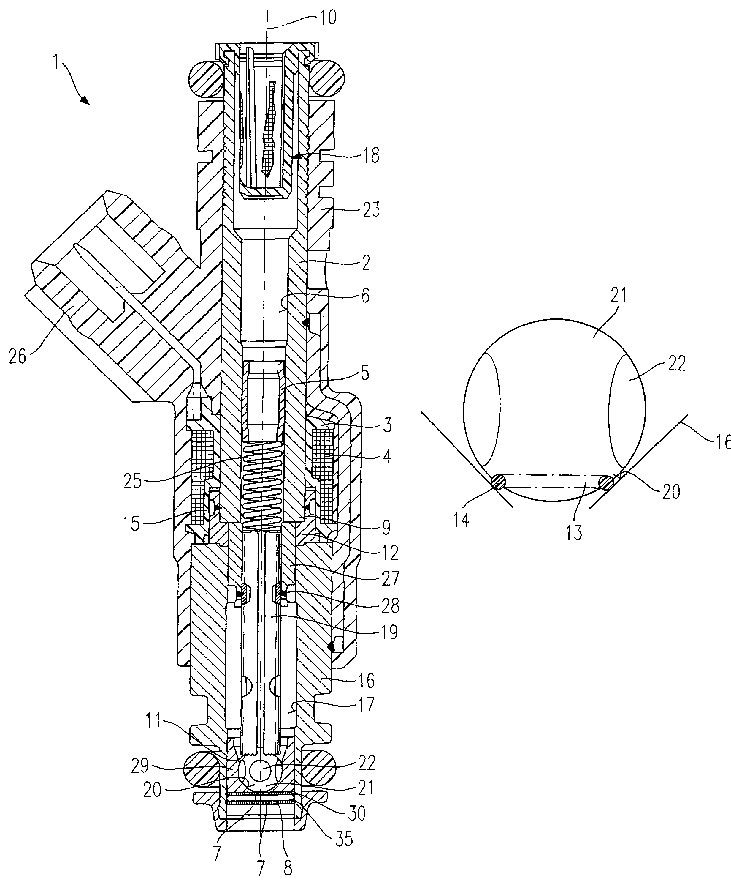
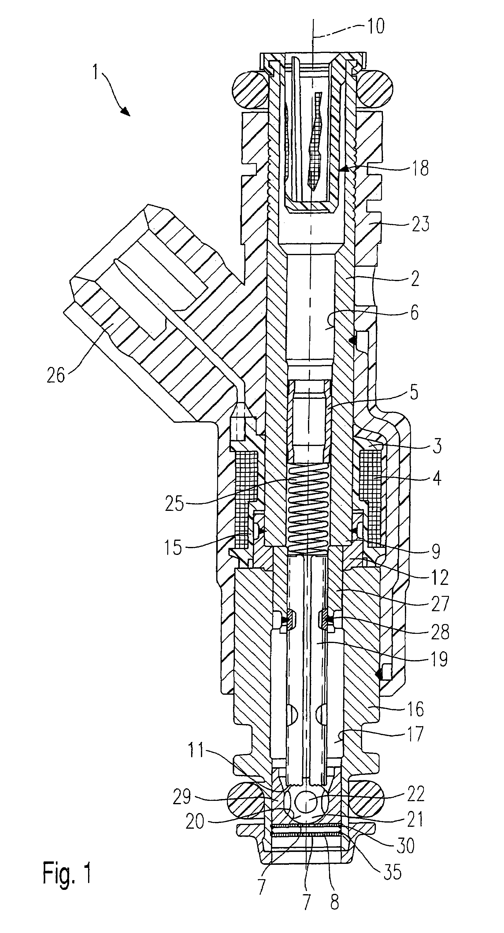
[0022]A fuel injector 1 shown in FIG. 1 is used, in particular, for the injection of water into the gas flow of a fuel cell (not shown further). Fuel injector 1 includes a core 2, which is used as intake nipple and is surrounded by a solenoid coil 4, core 2 being configured in the shape of a tube in this case and having a constant outer diameter over its entire length. However, it may also have a graded design. A coil shell 3 graded in the radial direction accommodates a winding of solenoid coil 4 and, in conjunction with core 2 having a constant outer diameter, enables fuel injector 1 to have an especially compact design in the region of solenoid coil 4. A tubular, metal intermediate part 12 is connected to a lower core end 9 of core 2, e.g. by welding, so as to form a seal and be concentric...


PUM

PropertyMeasurementUnit
temperatureaaaaaaaaaa
corrosion-aaaaaaaaaa
friction-aaaaaaaaaa

Abstract

A fuel injector for injecting water, in particular into the gas flow of fuel cells, has a valve needle having joined to its spray-discharge end a valve-closure member, which cooperates with a valve-seat surface formed on a valve-closure member a sealing seat. A spray-discharge orifice is provided downstream from the sealing seat, at least a portion of the surfaces of the fuel injector that come into contact with water being coated by a corrosion-inhibiting and / or friction-reducing coating.

Description

FIELD OF THE INVENTION[0001]The present invention relates to a fuel injector and to a method for manufacturing a fuel injector.BACKGROUND INFORMATION[0002]In fuel cells as they are commonly used in motor vehicles, in particular in the case of fuel cells having a proton-conducting polymer membrane, which are also known under the English term of proton exchange membrane fuel cell (PEM-FC) or polymer electrolyte fuel cell, the membrane forming the electrolyte must be kept moist at all times during operation. If the moisture drops below a certain value, the ion conductivity of the membrane decreases. To keep the moisture of the fuel cell membrane at a specific optimum level, deionized water is often metered to the supplied gas flow.[0003]The German Published Patent Application No. 199 53 803 describes a device for moistening the gas flow where water is added to the gas flow via a simple nozzle that projects into the gas flow.[0004]However, the water should be metered into the gas flow a...

Claims


Application Information

Patent Timeline
Patent Type & Authority Patents(United States)
IPC IPC(8): F02M51/00B05B1/30F02M51/06F02M61/16
CPCB05B1/302F02M51/0682F02M61/166F02M61/168Y10S239/04F02M2200/9038Y10T29/49405Y10S239/90F02M2200/02
Inventor MILLER, FRANK
Owner ROBERT BOSCH GMBH
Why Eureka
Try Eureka