Wire braid-reinforced microcatheter

a wire braided, micro-catheter technology, applied in the direction of catheters, coatings, etc., can solve the problems of high viscosity of embolizing materials, pressure may exceed the burst pressure of nearly all conventional pressure, etc., to achieve high degree of flexibility, high pressure, and high degree of strength

Active Publication Date: 2009-03-24
TYCO HEALTHCARE GRP LP
View PDF21 Cites 237 Cited by
  • Summary
  • Abstract
  • Description
  • Claims
  • Application Information

AI Technical Summary

Benefits of technology

[0011]We have now discovered a construction for microcatheters which provides the high degree of flexibility needed to traverse complicated small vessel pathways and the high degree of strength needed to withstand strenuous manipulation and the high pressures associated with catheter-delivery of viscous embolizing compositions.

Problems solved by technology

The high viscosity of the embolizing material poses a problem.
Such a pressure may exceed the burst pressure of nearly all conventional microcatheters.

Method used


Image

  • Wire braid-reinforced microcatheter
  • Wire braid-reinforced microcatheter
  • Wire braid-reinforced microcatheter

Examples


example 1

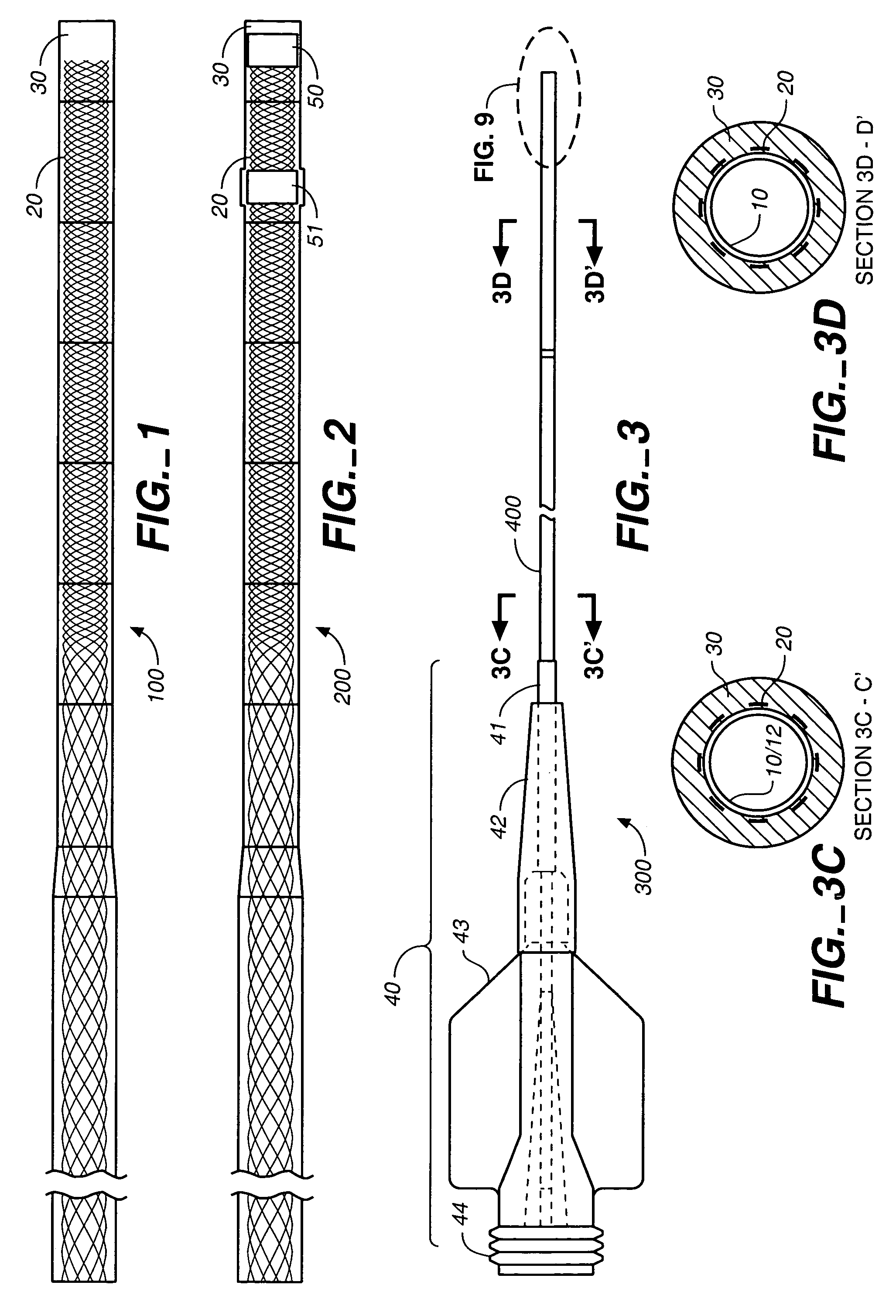
[0050]According to one example of the present invention, two catheters were formed of the materials and by the steps described below.

[0051]Two different Nitinol braids were cut to 155 cm in length for use in formation of the two catheters. The braids were each formed of eight elliptical 0.001″×0.003″ wires. The braids were formed on a steeger braider with the braider pitch changed between segments to form a continuous braid with a changing pitch The first braid had the following segments with the following pics-per-inch (ppi) starting from the distal end: 4 inches 120 ppi, 8 inches 70 ppi, 2 inches 40 ppi, 6 inches 30 ppi, and 39 inches 16 ppi. The second braid had the following segments starting from the distal end: 2 inches 120 ppi, 6 inches 110 ppi, 2 inches 50 ppi, 4 inches 40 ppi, 6 inches 30 ppi, and 39 inches 16 ppi. The remainder of the steps and materials were the same for the two catheters.

[0052]A liner of a polyimide layer overlapping a PTFE layer was purchased preloaded ...

example 2

[0058]A microcatheter was constructed as follows. A PTFE liner coated along its proximal end with polyimide was obtained. The polyimide coating was tapered between the coated and uncoated regions. The liner had an inside diameter of 0.17 inch (0.43 mm) and was more flexible in its uncoated region than in its coated region. This liner was placed on a suitable mandrel.

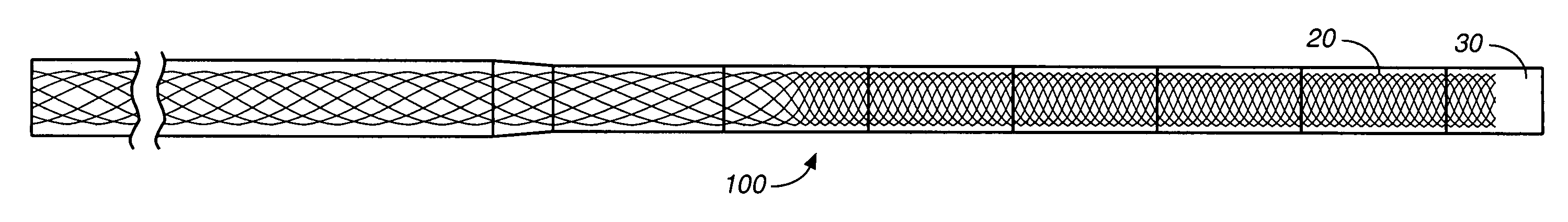
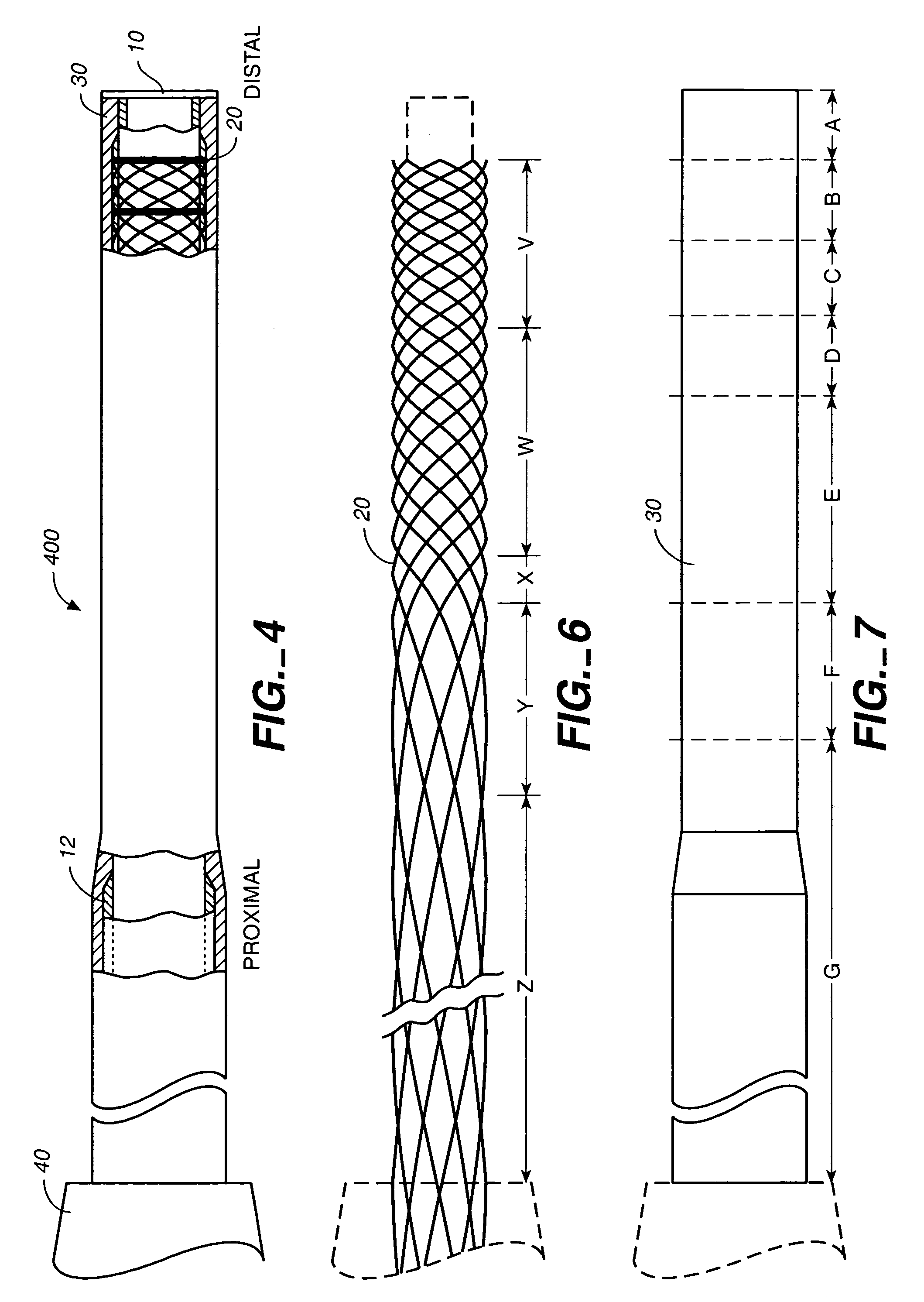
[0059]A Nitinol braid of the general type set out in Example 1 was obtained. This braid had 5 sections with the following five different pic per inch rates as shown in FIG. 6 and Table 3.

[0060]

TABLE 3NominalSectionSectionPic / InchLengthDistalV12015cm.W8015cm.X505cm.Y3015cm.ProximalZ25100+cm.

[0061]The braid was placed over the liner with the transition from 25 Pic to 30 Pic weave aligned somewhat distal to the end of the polyamide coating on the PTFE liner.

[0062]A polymer jacket was prepared by heat fusing seven cylindrical sections of polymers of varying stiffness to one another. The sections were fused beginning with the...

example 3

[0069]Example 2 was repeated with the following changes:

[0070]The wire braid was made of 0.003×0.0007″ elliptical wire, jacket section A was 25 durometer polyether / polyamide and the final outside diameter of the finished catheter was 1.7 F (0.57 mm—0.023″) at the distal end and 2.1 F (0.70 mm—0.028″) at the proximal end.


PUM

PropertyMeasurementUnit
diameteraaaaaaaaaa
inner diameteraaaaaaaaaa

Abstract

This invention is directed to a multi-layer catheter for navigation to remote locations within the body, comprising a liner layer, a braid layer and an outer jacket. The catheter provides a high degree of flexibility needed to traverse the vasculature and a high degree of strength needed to withstand the high pressures associated with catheter-delivery of viscous embolizing compositions.

Description

REFERENCE TO RELATED APPLICATION[0001]The application claims the benefit of U.S. Provisional Patent Application Ser. No. 60 / 417,182, filed on Oct. 10, 2002.FIELD OF THE INVENTION[0002]The invention relates to wire-reinforced catheters for navigation to remote locations within the body of a patient.DESCRIPTION OF THE RELATED ART[0003]Wire-reinforced catheters are well known in the art. Generally, these consist of an elongated, flexible tubular body defining a central lumen extending from one end of the body to the other end. A distal end of the catheter is delivered into the body of a patient and located at a treatment site. The proximal end of the catheter remains outside of the patient's body for manipulation by the treating physician. The lumen provides a conduit for delivery of material to or from the body, or for transfer of sensor information from within the interior of the body.[0004]Catheters vary in size from large diameter catheters for use in the urinary tract and in large...

Claims


Application Information

Patent Timeline
Patent Type & Authority Patents(United States)
IPC IPC(8): A61M25/00
CPCA61M25/0012A61M25/0053A61M25/0054A61M25/0045A61M2025/0042A61M2025/0046
Inventor HEWITT, TODD J.MARTEL, MICHAEL D.DAVIS, PETER
Owner TYCO HEALTHCARE GRP LP
Why Eureka
Try Eureka