Air cleaner

a technology for air cleaners and cleaners, applied in the field of air cleaners, can solve the problems of fuel adsorption, fuel consumption and engine output are adversely affected, wear powder of active carbon tends to be generated, etc., and achieve the effect of maintaining a fuel adsorption function, reducing ventilation resistance, and preventing damage to a fuel adsorption member

Inactive Publication Date: 2009-03-24
TOYOTA BOSHOKU KK
View PDF17 Cites 18 Cited by
  • Summary
  • Abstract
  • Description
  • Claims
  • Application Information

AI Technical Summary

Benefits of technology

[0011]An objective of the present invention is to provide an air cleaner capable of lowering a ventilation resistance, preventing a damage of a fuel adsorption member, maintaining a fuel adsorbing function high over a long term, and preventing an engine malfunction.

Problems solved by technology

Accordingly, a ventilation resistance is increased, and there is a risk that a fuel consumption and an engine output are adversely affected.
Further, a wear powder of the active carbon tends to be generated by a friction between the active carbons and a friction between the active carbon and a fiber retaining the active carbon.
For these reasons, not only a fuel adsorbing function of the active carbon is lowered, but also there is a risk that a fragment of the fuel adsorption members 101, the wear powder of the active carbon or the like is sucked into the engine so as to cause an engine malfunction.
Therefore, the surface of the fuel adsorption member 113 tends to be damaged by the impact pressure and the heat of the backfire.
Accordingly, even if the resin formed of the emulsion is porous, the fuel adsorbing function of the active carbon is limited to a large degree because the surface of the active carbon is covered with the resin.
In the structure shown in FIG. 16, since the air flow path is obstructed by the fuel adsorption member 121, there is a risk that the ventilation resistance is increased, and the fuel consumption and the engine output are adversely affected.
Therefore, in accordance with the conventional structures, it is impossible to sufficiently satisfy the demand for a reduction of the ventilation resistance, the fuel adsorbing function of the fuel adsorption member, and durability.

Method used


Image

  • Air cleaner
  • Air cleaner
  • Air cleaner

Examples


first embodiment

[0036]A description will be given below of a first embodiment in accordance with the present invention with reference to FIGS. 1 to 7.

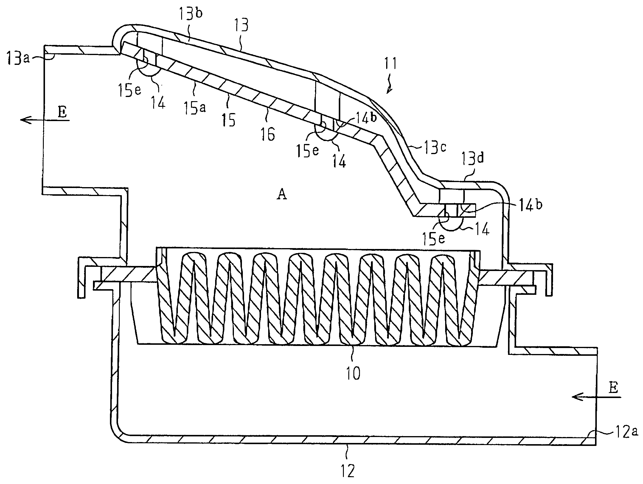
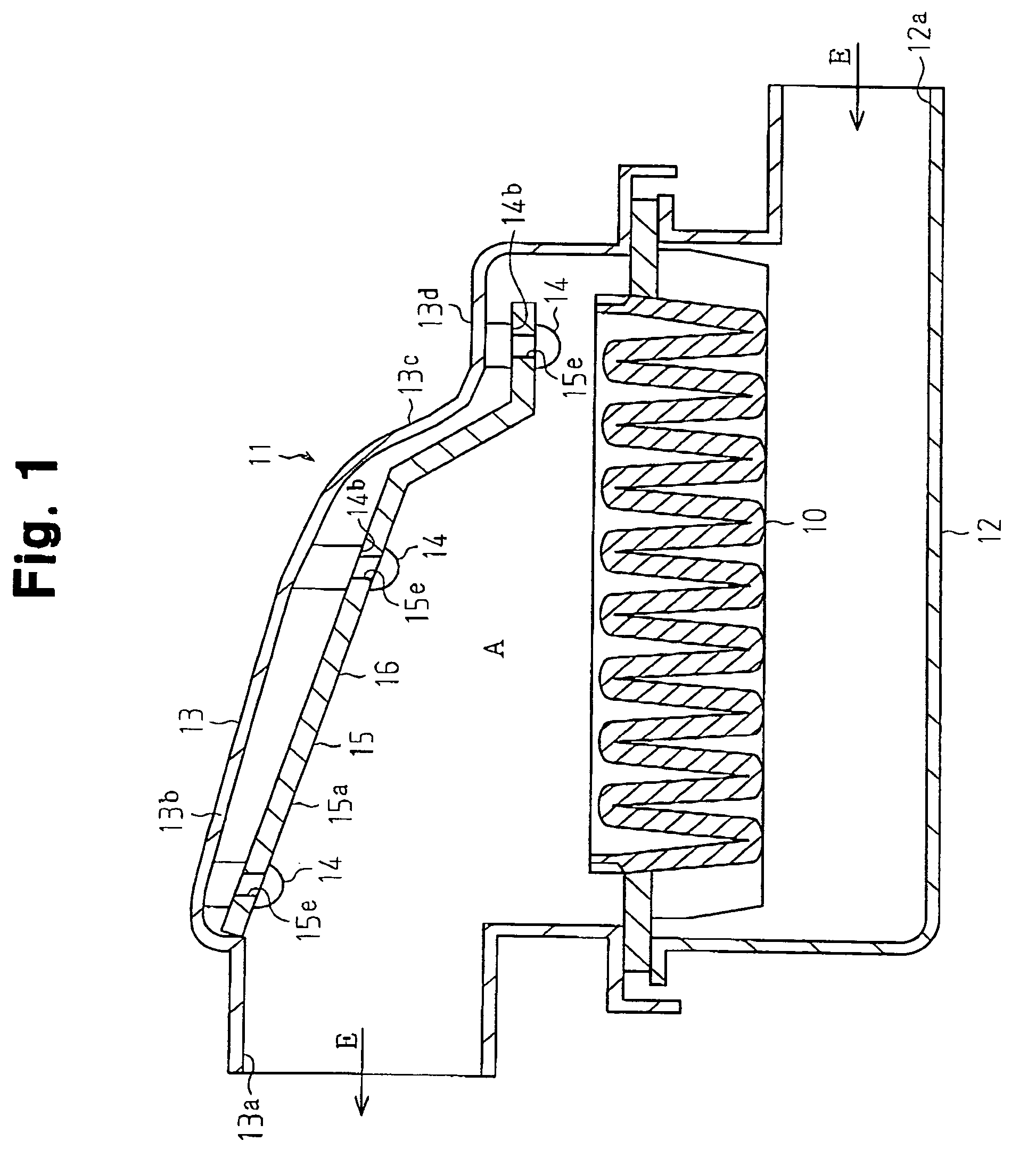
[0037]As shown in FIG. 1, a case of an air cleaner 11 is formed by a first housing 12 and a second housing 13. The first housing 12 has an inlet port 12a, and an upper face of the first housing 12 is opened. The second housing 13 has an outlet port 13a, and a lower face of the second housing 13 is opened. A filter element 10 filtrating an air sucked to an engine is arranged between the first housing 12 and the second housing 13. The filter element 10 is arranged in such a manner as to intersect a flow path A of an intake air E reaching to the outlet port 13a from the inlet port 12a.

[0038]An upper wall portion of the second housing 13 is provided with a first top wall portion 13b adjacent to the outlet port 13a, a slant wall portion 13c adjacent to the first top wall portion 13b, and a second top wall portion 13d adjacent to the slant wall portion 13c...

second embodiment

[0058]Next, a description will be given of a second embodiment in accordance with the present invention with reference to FIG. 8. In the description of the second embodiment and each of the subsequent embodiments, the description will be given mainly of different portions from the first embodiment.

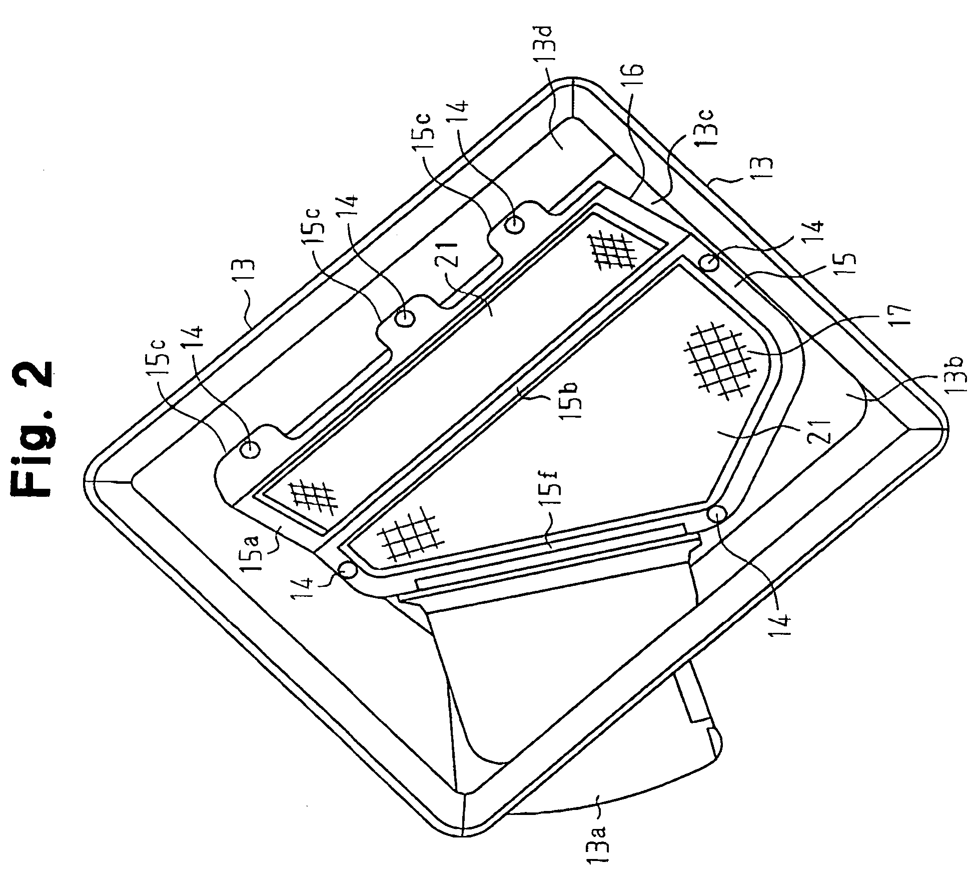
[0059]As shown in FIG. 8, the intermediate frame portion 15b of the frame 15, the outer peripheral frame portion 15a near both ends of the intermediate frame portion 15b, and a portion 15g of the outer peripheral frame portion 15a near each of the protruding pieces 15c are formed thinner than the corresponding portions in the first embodiment. Accordingly, it is easy to bend the fuel adsorption member 16 in the thinned portions.

[0060]In accordance with the second embodiment, it is possible to obtain the following advantage.

[0061](9) It is easy to bend the frame 15 even after forming the frame 15. Accordingly, even if the fuel adsorption member 16 is formed in a flat shape, it is possible t...

third embodiment

[0062]Next, a description will be given of a third embodiment in accordance with the present invention with reference to FIG. 9.

[0063]As shown in FIG. 9, the adsorption sheet member 17 is formed along three surfaces comprising the inner surface of the first top wall portion 13b, the inner surface of the slant wall portion 13c and the inner surface of the second top wall portion 13d.

[0064]In accordance with the third embodiment, it is possible to obtain the following advantage.

[0065](10) The adsorption sheet member 17 has a wider fuel vapor adsorbing area than the first embodiment. Accordingly, it is possible to improve the fuel adsorbing function of the fuel adsorption member 16.


PUM

PropertyMeasurementUnit
stress concentrationaaaaaaaaaa
adsorptionaaaaaaaaaa
heat resistanceaaaaaaaaaa

Abstract

A fuel adsorption member 16 is fixed to an inner surface of a housing 13 by fixing pins 14. A fuel vapor leaking from an intake system of an engine is adsorbed by an active carbon included in an adsorption sheet member of the fuel adsorption member 16. The fuel adsorption member 16 is arranged along an inner surface of the housing 13. Accordingly, when an engine is operated, the fuel adsorption member 16 can reduce a ventilation resistance without being adversely affecting an intake air E. Further, the fuel adsorption member 16 is fixed to an inner surface of the housing 13 in accordance with a swaging of the fixing pins 14. Therefore, it is possible to prevent a damage of the fuel adsorption member 16 caused by a vehicle vibration, a fluctuation of an intake pressure or the like, and a reduction of a fuel adsorbing function caused by a wear of the active carbon.

Description

BACKGROUND OF THE INVENTION[0001]The present invention relates to an air cleaner provided with a fuel adsorption member for adsorbing a fuel vapor leaking from an intake system of an engine.[0002]This kind of air cleaner is disclosed, for example, in Japanese Laid-Open Patent Publication No. 2001-263177, Japanese Laid-Open Patent Publication No. 2001-336454 and Japanese Laid-Open Patent Publication No. 2003-42017.[0003]The air cleaner described in Japanese Laid-Open Patent Publication No. 2001-263177 is provided with sheet-like fuel adsorption members 101 including an active carbon having a fuel adsorbing function, as shown in FIGS. 13 and 14. The fuel adsorption members 101 are arranged downstream of a filter element 102, and is attached within a housing 104 in a hanged state. In this structure, at an engine stop time when an intake air E does not exist, the fuel adsorption members 101 are in a hanged state due to its own weight, as shown by solid lines in FIGS. 13 and 14. At this ...

Claims


Application Information

Patent Timeline
Patent Type & Authority Patents(United States)
IPC IPC(8): B01D53/02F02M33/02
CPCB01D46/0036F02M25/0854F02M35/024
Inventor MIZUTANI, YOSHIROSHIBATA, YASUFUMI
Owner TOYOTA BOSHOKU KK
Why Eureka
Try Eureka