Fault-tolerant synchronisation device for a real-time computer network

a real-time computer network and fault-tolerant technology, applied in the field of fault-tolerant real-time computer network hardware and software, can solve problems such as lack of system versatility, and achieve the effect of less accuracy and greater distances

Inactive Publication Date: 2009-03-24
THALES SA
View PDF20 Cites 6 Cited by
  • Summary
  • Abstract
  • Description
  • Claims
  • Application Information

AI Technical Summary

Benefits of technology

[0005]The device according to the invention can be used for reliable synchronization over several tens of meters and allows the choice of including or not including in the synchronization any equipment connected to the network

Problems solved by technology

The drawbacks of this state of the art are basically the short distance over which reliable synchronization is possible (approximately a meter owing to the need for a ground reference comm

Method used


Image

  • Fault-tolerant synchronisation device for a real-time computer network
  • Fault-tolerant synchronisation device for a real-time computer network
  • Fault-tolerant synchronisation device for a real-time computer network

Examples


Embodiment Construction

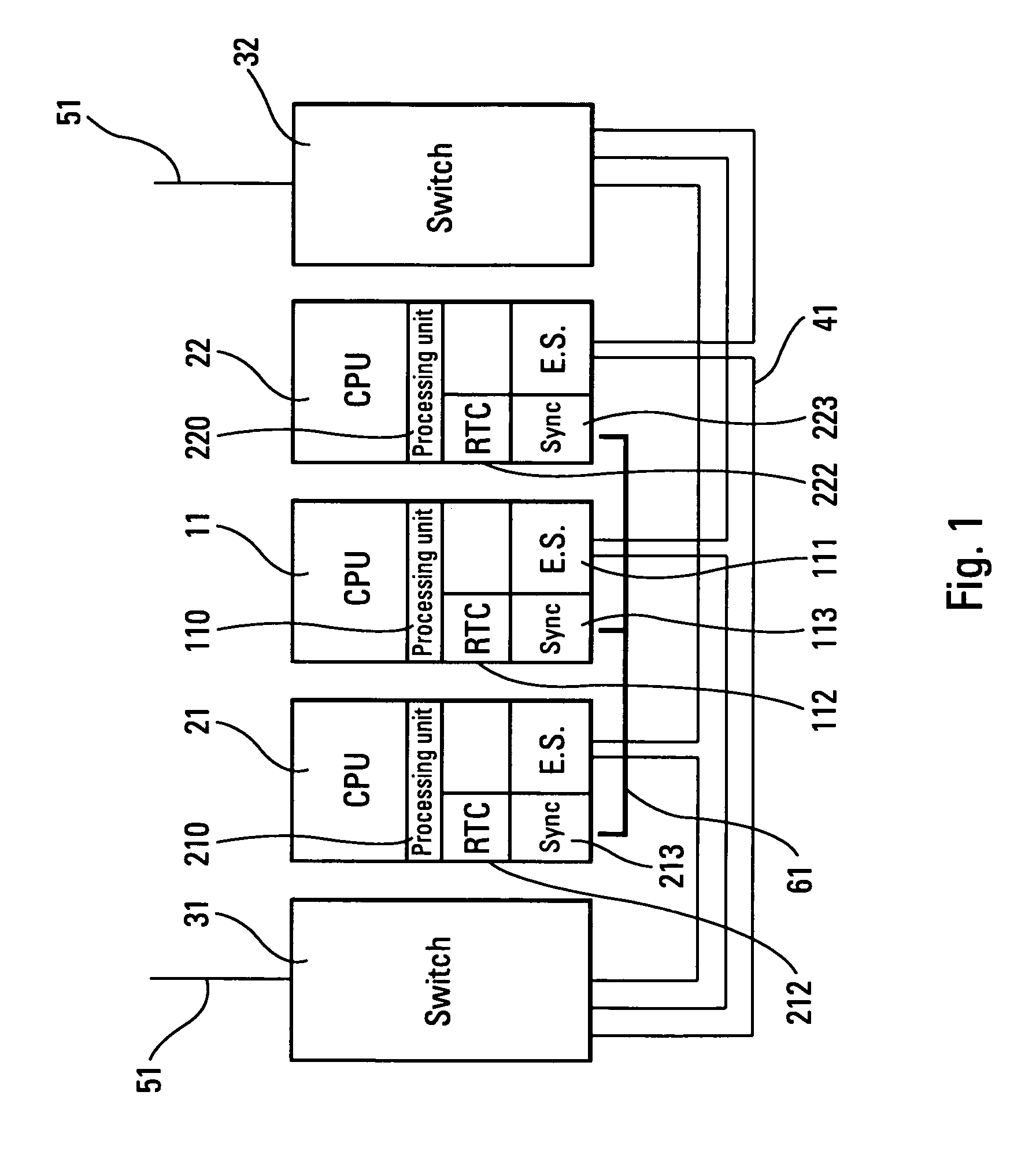
[0014]The computer platform in FIG. 1 includes at least one central processing unit or CPU 11, 21, 22, and cabinet switches 31, 32. The CPU 21, 22 can also be input / output (or I / O) units. This equipment is interconnected via a duplex data network 41 for example of the Full Duplex 100 MHz Ethernet type. The platform shown is connected to other different platforms via the switches 31, 32 and the bus 51.

[0015]The central processing units 11, 21, 22 each include an actual processing system 110, 210, 220 where the specific processing of the unit and the control of the data network are carried out via the End System or ES 111, a real-time clock or RTC 112, and a synchronization entity or Sync entity 113, 213, 223 according to the embodiments of the present invention.

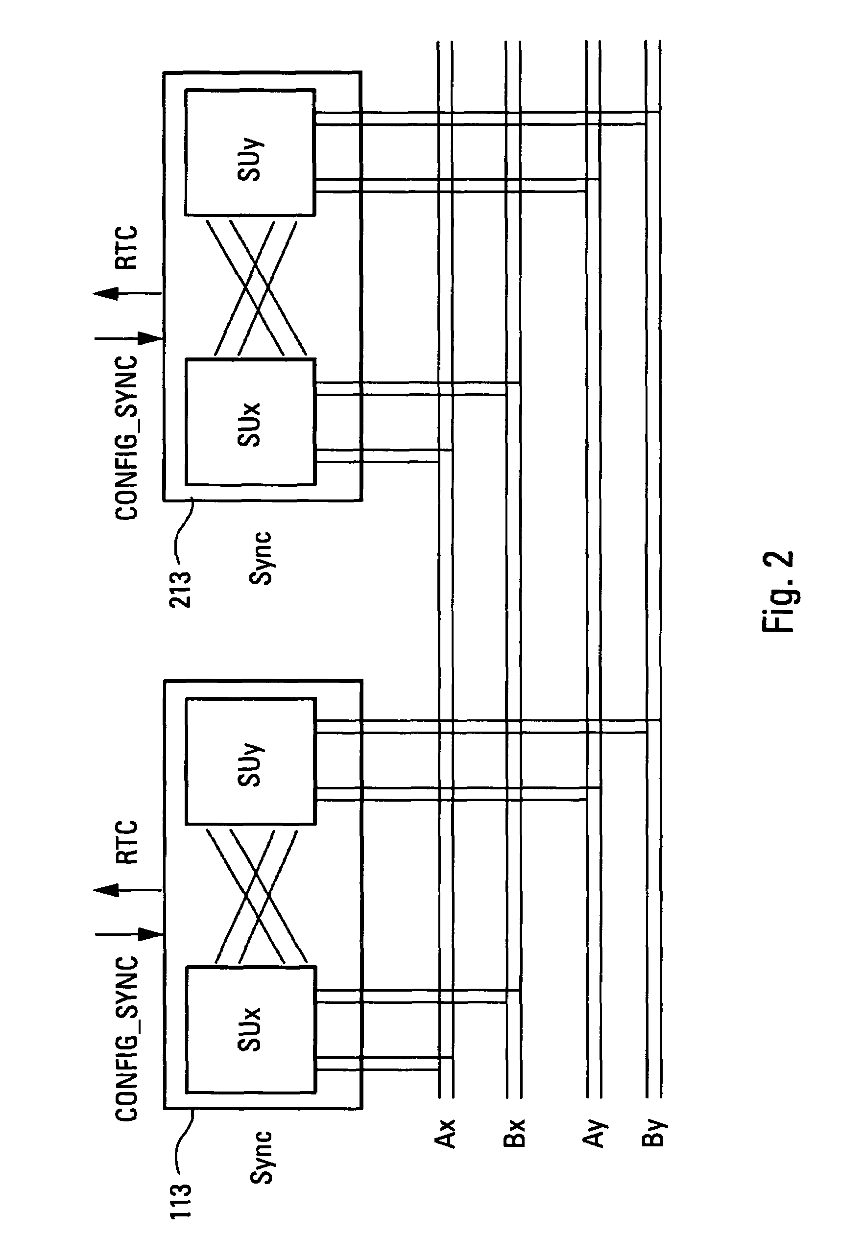
[0016]The synchronization entities 113, 213, 223 are interconnected via a specific synchronization bus 61 separate from the data link 41, details of whose specific embodiments are provided farther on in the description.

[0017]R...


PUM


Abstract

Fault-tolerant synchronization of real-time equipment connected to a computer network of several tens of meters with an option of including or not including such equipment in the synchronization device is disclosed. Global scheduling of the real-time computer platform in the form of minor and major cycles is provided in order to reduce latency during sensor acquisition. The associated calculation and preparation of output to the actuator is provided in an integrated modular avionic (IMA) architecture. To achieve the foregoing, a synchronization bus separate from the data transfer network and circuits interfacing with this specific bus for processing the local real-time clocks in each piece of equipment in a fault-tolerant, decentralized manner is provided.

Description

FIELD OF INVENTION[0001]The present invention belongs to the field of hardware and software for fault-tolerant real-time computer networks. More specifically, it relates to the synchronization of equipment connected to said network.[0002]The problem to be solved is the failure-free phasing of the real-time clocks of processing equipment connected by one or more data transfer networks. The fact of a reliable solution being provided to this problem is particularly important for the latency of data in the case of equipment on board aircraft, especially that which fulfills the functions of alarm, autopilot, flight plan, maintenance or service management.BACKGROUND OF THE INVENTION[0003]The relevant state of the art is represented by U.S. Pat. Nos. 5,307,409, 5,343,414, 5,386,424 and 5,557,623. These systems further form the subject of an ARINC 659 standard (Dec. 27, 1993) corresponding to a data transfer system via backplane bus.[0004]The drawbacks of this state of the art are basically...

Claims


Application Information

Patent Timeline
IPC IPC(8): G06F1/12G06F11/16G06F11/18
CPCG06F1/12G06F11/1604G06F11/1679G06F11/18
Inventor TOILLON, PATRICECOLAS, GERARD
Owner THALES SA
Why Eureka
Try Eureka