Inferential temperature control system

a temperature control system and temperature control technology, applied in the direction of liquid transfer devices, semiconductor/solid-state device testing/measurement, instruments, etc., can solve the problems of system shutdown, product waste, product and/or equipment waste, etc., to achieve the effect of reducing production costs, reducing production costs, and reducing production efficiency

Inactive Publication Date: 2009-03-31
NORDSON CORP
View PDF15 Cites 86 Cited by
  • Summary
  • Abstract
  • Description
  • Claims
  • Application Information

AI Technical Summary

Benefits of technology

[0007]The present invention provides a system that manages the temperature of thermoplastic material used in manufacturing by initiating a default heating cycle in response to a sensor failure. The system thus continues to heat the thermoplastic material according to the default heating cycle until, for instance, the faulty sensor, connective wiring and / or other sensor-related component can be repaired or replaced. This feature reduces the occurrence of unscheduled downtime.

Problems solved by technology

Unregulated temperatures can lead to ineffective viscosities, wasted product and / or damaged equipment.
Left uncorrected, undetected and / or unregulated temperatures resulting from a failed sensor will cause wasted product, as well as malfunctioning or damaged equipment.
As a consequence, systems typically shut down production after a sensor or other component failure is detected.

Method used


Image

  • Inferential temperature control system
  • Inferential temperature control system
  • Inferential temperature control system

Examples


Embodiment Construction

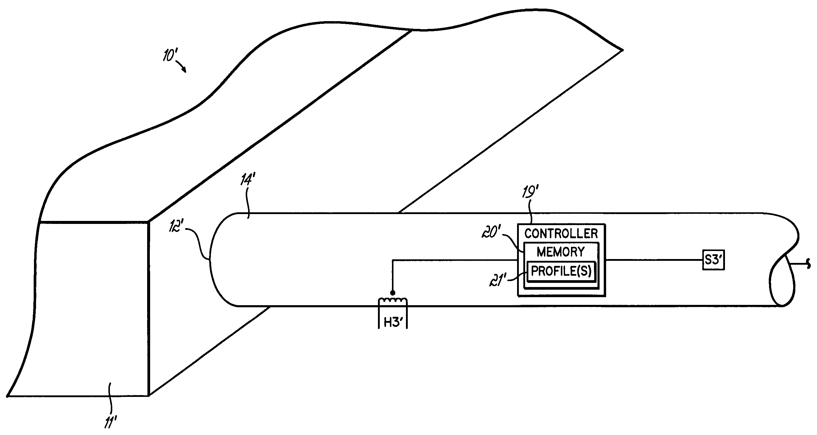
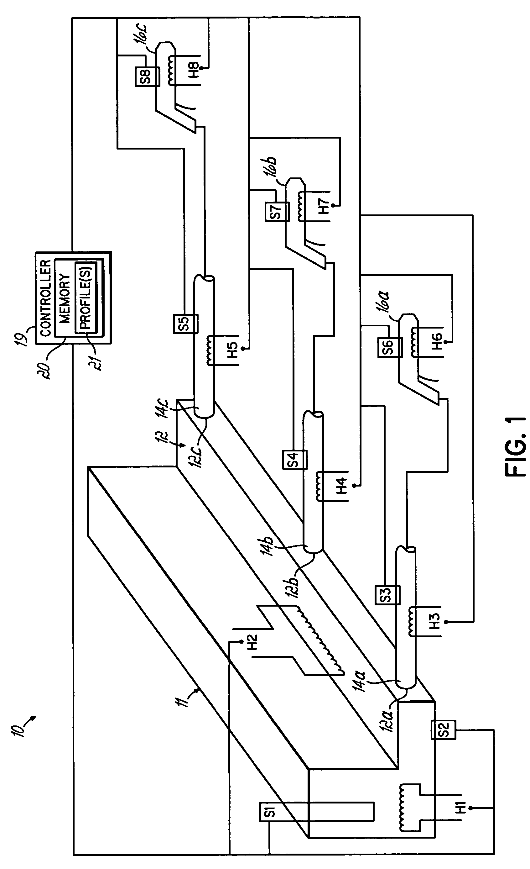
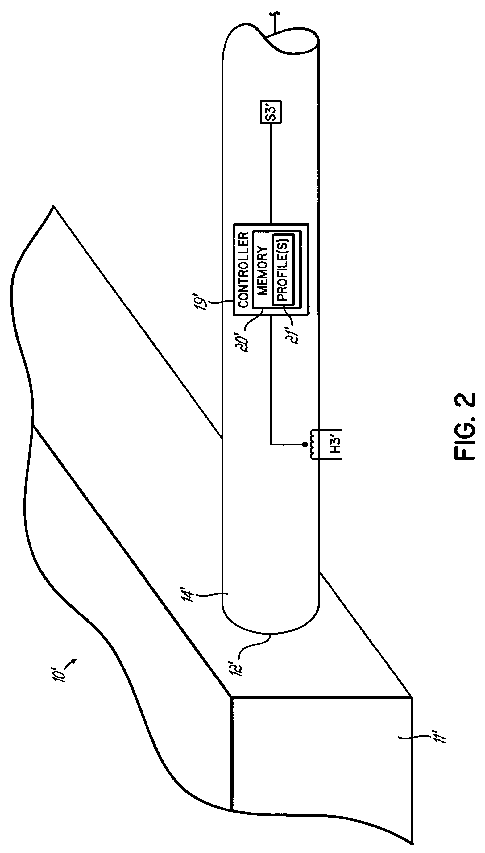
[0016]FIG. 1 illustrates a hot melt heating and dispensing system 10 configured to implement a default heating cycle in response to a detected component failure. More particularly as shown in FIG. 1, the system 10 includes a tank, or reservoir 11. The reservoir 11 is fluidly coupled to a manifold 12 for distributing the liquefied thermoplastic material such as a hot melt adhesive. One or more heated hoses 14a-c may be attached to the manifold and to a respective dispenser 16a-c.

[0017]The reservoir 11 is provided with a schematically depicted heater, or heater H1. Associated with the reservoir 11 is temperature sensor S1, also shown schematically. As with other heaters described herein, heater H1 may be configured such that it is incapable of causing the liquid to exceed the flashpoint temperature of heated adhesive, should for instance, a switch or contact associated with the heater H1 become locked and incapable of turning off the heater.

[0018]The manifold 12 has several output po...


PUM


Abstract

A system manages the temperature of thermoplastic material by initiating a default heating cycle in response to a sensor failure. The system may thus continue to heat the thermoplastic material according to the default heating cycle until the sensor can be repaired or replaced. A system controller implements the default heating cycle using a stored profile. That is, the controller causes a heating element to generate heat according to a default heating profile retrieved from a memory. The profile may be determined using historical heating data, user input and / or a factory setting.

Description

FIELD OF THE INVENTION[0001]This invention relates generally to systems used to manufacture products incorporating thermoplastic products, and more particularly, to systems that monitor the operation of sensors and other components during a thermoplastic heating application.BACKGROUND OF THE INVENTION[0002]Thermoplastic materials are used in a variety of industrial applications that include adhesive dispensing and heat sealing applications. Thermoplastic material is processed to produce, among numerous other products, diapers, shrink wrap packages, sanitary napkins and surgical drapes. The technology has evolved from the application of linear beads, or fibers of material and other spray patterns, to air assisted applications, such as spiral and melt-blown depositions of fibrous material.[0003]A number of these and other industrial applications involve stringent regulation and maintenance of system temperatures to mitigate occurrences of over or under heating. Unregulated temperature...

Claims


Application Information

Patent Timeline
Patent Type & Authority Patents(United States)
IPC IPC(8): H01L21/00B67D7/80B67D7/14
CPCB05C11/1042B05C11/1044
Inventor RATERMAN, JOHN M.
Owner NORDSON CORP
Why Eureka
Try Eureka