Vehicle mounted image processor and method of use

a technology of image processor and vehicle, which is applied in the field of vehicle mounted image processor, can solve the problems of miscalculation of the position of the vanishing line for the current frame, and achieve the effect of eliminating the effect of pitching and high precision

Active Publication Date: 2009-03-31
NISSAN MOTOR CO LTD
View PDF8 Cites 17 Cited by
  • Summary
  • Abstract
  • Description
  • Claims
  • Application Information

AI Technical Summary

Benefits of technology

[0003]Accordingly, there is provided an apparatus wherein images in an individual from photographed by an imaging means are processed to calculate velocity information for individual pixel images, a velocity information set for which the relative positions between velocity information in images do not change between frames is specified as an observation point group, from the plurality of velocity information calculated, the movement of the specified observation point group in an image is observed to detect pitching of the vehicle, and any two points of differing height on an object present in an image are extracted as feature points, the effect of pitching is eliminated from the feature points, and based on the velocity ratio in the image of the feature points after eliminating the length between the two feature points and the effect of pitching, the position of a vanishing line in the image is calculated. With the present invention, any two points of differing height on an object present in an image are extracted as feature points and the position of a vanishing line in the image is calculated based on the velocity ratio of the feature points in the image after the length between the two feature points and the effect of pitching is eliminated. Because of this, the vanishing line position in the image can be calculated with high precision.

Problems solved by technology

There may be instances, however, where this may result in the position of the vanishing line for the current frame being miscalculated when movement of an object in the vertical orientation between frames is detected as a result of a change in the relative distance between the vehicle and the object.

Method used


Image

  • Vehicle mounted image processor and method of use
  • Vehicle mounted image processor and method of use
  • Vehicle mounted image processor and method of use

Examples


Embodiment Construction

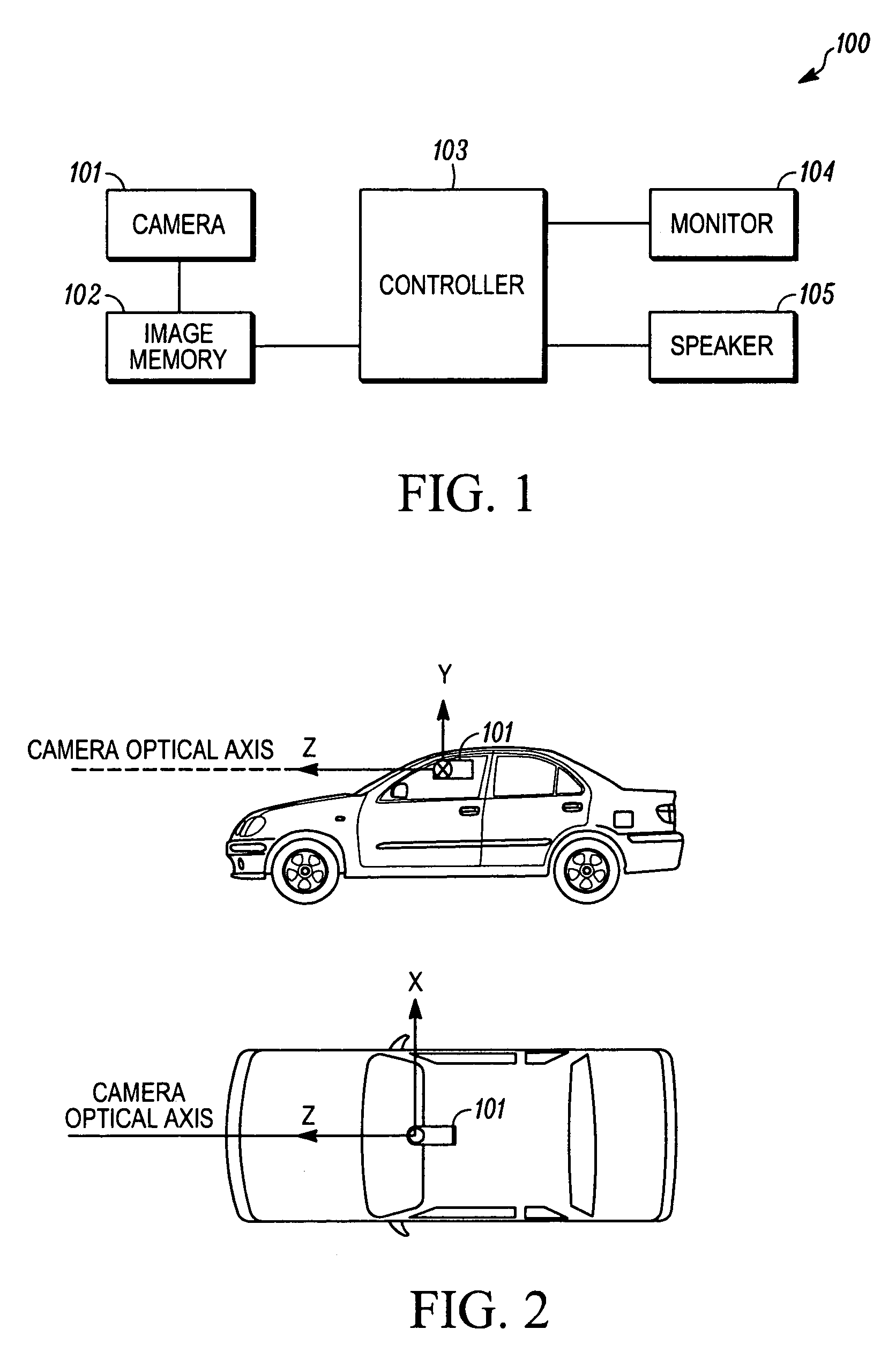
[0016]FIG. 1 is a functional block diagram showing an image processor 100 that may be mounted to a vehicle. Image processor 100 may include a camera 101 for photographing images in front of the vehicle, an image memory 102 for storing images photographed by camera 101, a controller 103, a monitor 104 for viewing images photographed by camera 101, and a speaker 105 for outputting a warning tone to the operator.

[0017]Referring also to FIG. 2, camera 101 is a high-speed camera that has an imaging element, such as a CCD or CMOS, that continually photographs images in front of the vehicle at an extremely small constant time interval Δt, for example 2 milliseconds (frame rate=500 fps (frames per second)), while the vehicle is traveling, and outputs individual frames to image memory 102. Camera 101 may be mounted in the upper part at the front of the vehicle interior, or any other location that provides a reasonably unobstructed view of the front of the vehicle. A visual axis Z of camera 1...


PUM


Abstract

A vehicle-mounted detecting device and corresponding method for detecting a distance between the vehicle and an object outside the vehicle. The detecting device extracts edge intersection points from images of individual frames photographed by a camera. A set of edge intersection points for which the relative position in images does not change between frames is then specified as an observation point group; the movement of the specified observation point group in images is observed; and pitching by the vehicle is detected. Any two points with differing heights on an object present in an image are extracted as feature points, and after the effect of pitching is eliminated from the feature points, the position of a vanishing line in the image is calculated based on the ratio of the velocities of the feature points in images after the length between the two feature points and the effects of pitching are eliminated.

Description

TECHNICAL FIELD[0001]The present invention relates in general to automotive vehicles and more particularly to a vehicle-mounted image processor for processing images photographed by a camera and an image processing method.BACKGROUND[0002]Detectors for detecting relative distance between objects are known. One such detector is disclosed in Japanese Kokai Patent Application No. 2001-084497. With this position detector, the amount of movement in the vertical orientation between picture frames for an object detected on photographed images can be measured and the amount of change in the vehicle pitching angle can be calculated based on the amount of movement. However, in the existing device, the amount of pitching change in the current frame is calculated based on the amount of movement in the vertical orientation of an object between frames, which is added to the vanishing line position in the previous frame, and the vanishing line position in the current frame is calculated. There may ...

Claims


Application Information

Patent Timeline
Patent Type & Authority Patents(United States)
IPC IPC(8): G06F17/00G06K9/00
CPCG06T7/0042G06T7/0061G06K9/00805G06T7/73G06T7/536G06V20/58
Inventor NISHIUCHI, HIDEKAZU
Owner NISSAN MOTOR CO LTD
Why Eureka
Try Eureka