Rotating concentric holdown

a concentric hold-down and rotation technology, applied in the direction of rod connection, shock-proofing, manufacturing tools, etc., can solve the problems of increasing non-uniform compression stress on the underlying structural member, structural failure, and heavy and costly production, and achieve the effect of rotating more smoothly

Active Publication Date: 2009-04-07
SIMPSON STRONG TIE
View PDF73 Cites 28 Cited by
  • Summary
  • Abstract
  • Description
  • Claims
  • Application Information

AI Technical Summary

Benefits of technology

[0013]An object of the present invention is to reduce bending moments in the wood wall stud or post at the juncture of the top of the holdown connector and the wall stud or post.
[0015]The present invention is a connector with substantially arcuate, or curvilinear, tapering portions which allow the connector to rotate more smoothly than with angularly tapering portions.
[0016]The present invention is a connection in which the tapered support surface of the support base conforms to the registering tapered portions of the connector, allowing the connector to rotate smoothly against the support base.

Problems solved by technology

Earthquakes, hurricanes, tornadoes and floods all impose forces on a building that can cause structural failure.
They were heavy and costly to produce, in particular because of the additional labor involved in welding and painting.
Prior art holdowns, as described above, do not allow post rotation at the bottom, and bending stresses are introduced into the post above the holdown during shear wall movement.
Prior art holdowns, however, have not allowed rotation to occur at that point, but have instead permitted bending in the wood post at the juncture of the top of the holdown and the supported post.
As the load line of action moves away from the center of the holdown, the compression stresses on the underlying structural member become increasingly non-uniform.
This is undesirable because it tends to rupture the progressively bending upright post member and to damage the underlying structural member, usually a concrete foundation, which both supports and anchors the structure above it.
Recently, it has become apparent that simply increasing the strength of holdowns does not necessarily result in the best connection for the most common installation, between a frame wall reinforced for shear resistance and a concrete foundation.
By transferring failure entirely out of the holdowns, the risk of catastrophic failure of the connected structure is increased.
This results in more gradual and predicable failure.

Method used


Image

  • Rotating concentric holdown
  • Rotating concentric holdown
  • Rotating concentric holdown

Examples


Embodiment Construction

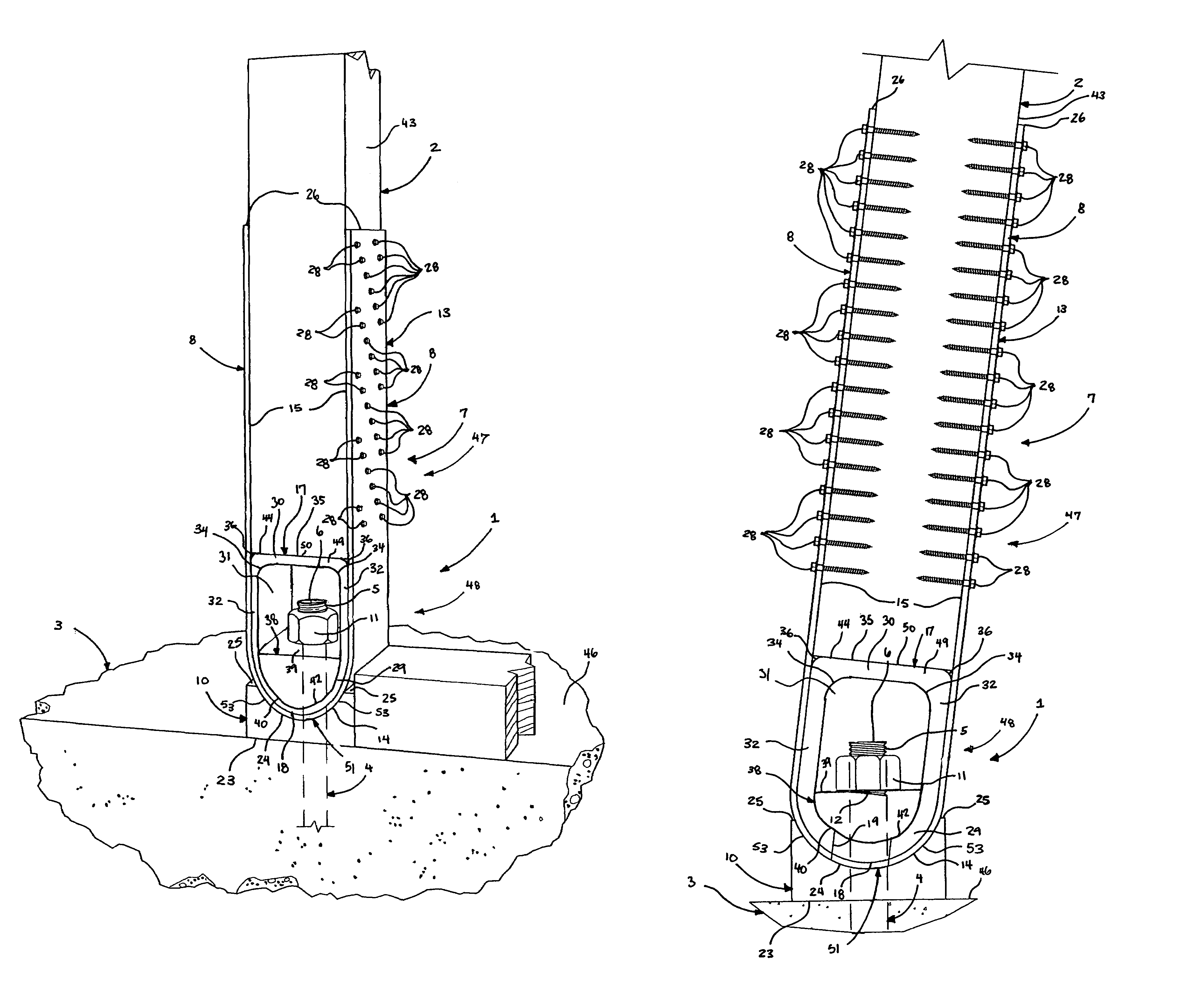
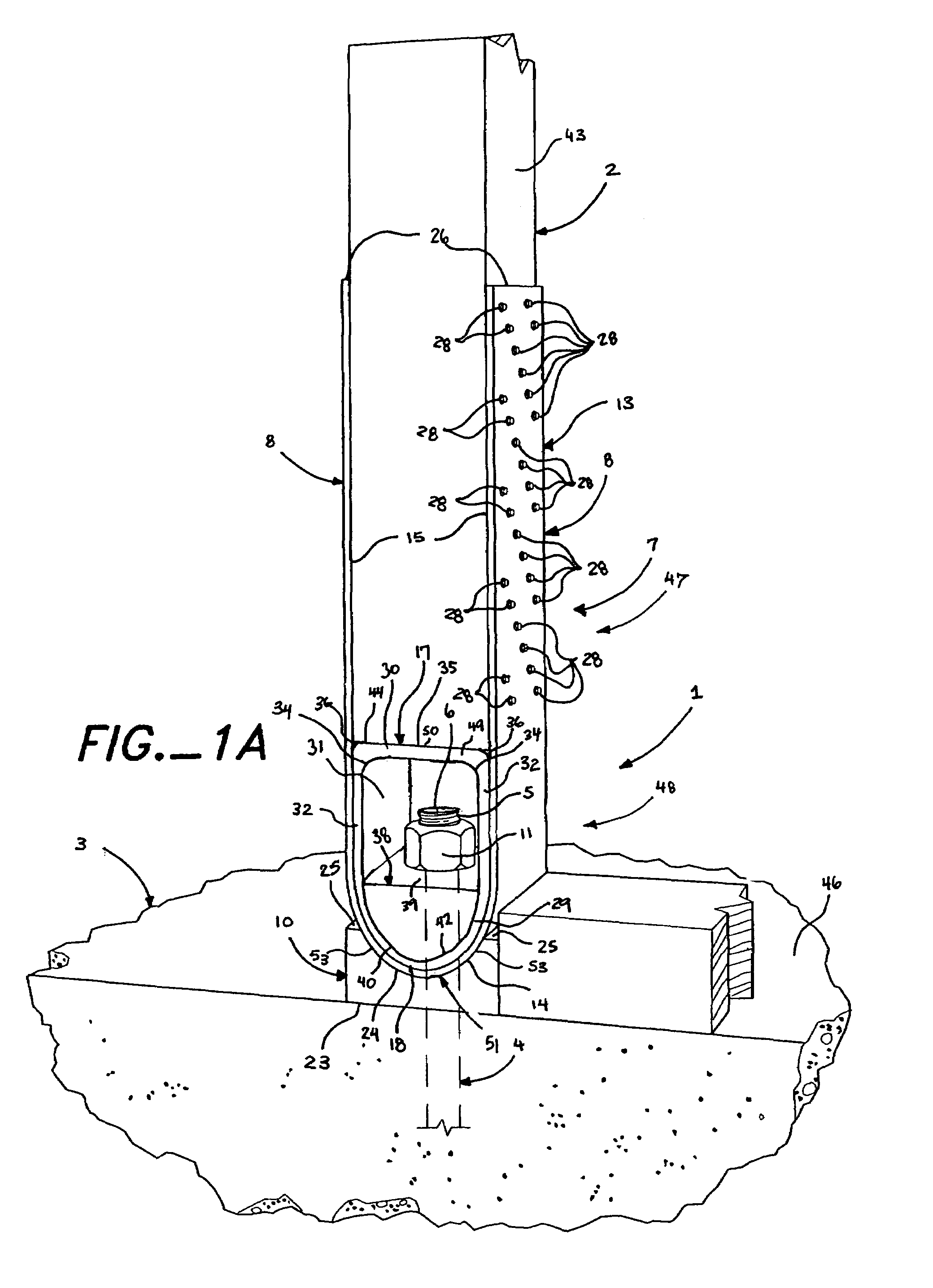
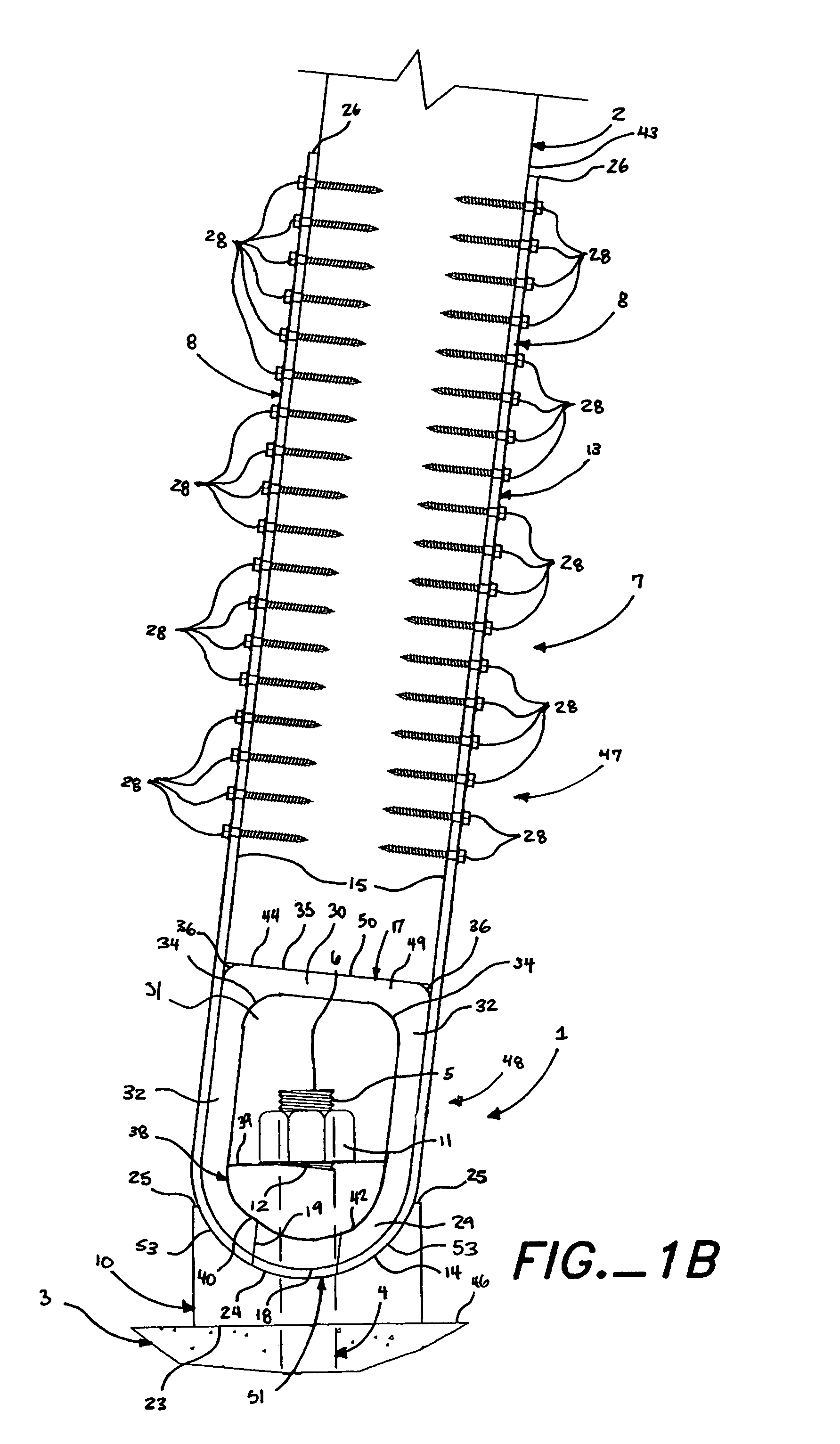
[0054]As shown in FIGS. 1A, 1B, 10 and 15A-19, the present invention is a building connection 1 including a first building structural member 2, a second building structural member 3, a first anchor member 4, and a connector 7 that receives the first end portion 5 of the first anchor member 4. As shown in FIGS. 1B, 10 and 15B, the connection 1 has an axis of rotation 12 and the axis of rotation 12 is below the first end 6 of the first anchor member 4.

[0055]The first building structural member 2 includes a first side face 43 and a bottom end 44, the bottom end 44 having a width 45, as shown in FIG. 19. The second building structural member 3 includes an upper surface 46 that supports the first building structural member 2. The first anchor member 4 is restrained by the second building structural member 3; the first anchor member 4 further includes a first end portion 5 extending from the second building structural member 3 and a first end 6.

[0056]The connector 7 includes an upper port...


PUM


Abstract

A connection between a wall stud or post and an anchor bolt embedded in a concrete foundation, using a holdown connector that attaches to the anchor bolt and supports the wall stud or post above it. The holdown connector has a tapered bottom that allows it to rotate laterally, allowing the connection to act more purely in tension than is possible with a rigid connection.

Description

BACKGROUND OF THE INVENTION[0001]The present invention relates to a connector for anchoring a first building structural member to a second building structural member. The connector works in conjunction with a separate anchor member that is received or attached to the second building structural member and with fasteners for attaching the connector to the first building structural member.[0002]Earthquakes, hurricanes, tornadoes and floods all impose forces on a building that can cause structural failure. To counteract these forces, it has become common practice to add or strengthen ties between the structural members of a building in the area of the building where these cataclysmic forces may be concentrated. For example, framed walls can be connected to the foundation rather than merely rest on it. Connections between the framed walls of each floor can be strengthened. And joists can be connected to both their headers and the walls that support the headers. One of the most common con...

Claims


Application Information

Patent Timeline
Patent Type & Authority Patents(United States)
IPC IPC(8): E04B1/21
CPCE02D27/42E04H12/2253Y10T403/4605Y10T403/4621
Inventor PRYOR, STEVEN E.AREVALO, RICARDO
Owner SIMPSON STRONG TIE
Why Eureka
Try Eureka