
Super compressed detonation method and device to effect such detonation

a super-compressed, energy-sensitive technology, applied in the direction of explosive charges, weapons, projectiles, etc., can solve the problems of inability to provide detonation in super-compressed energy-sensitive materials, limited techniques to observation, and produced extremely high pressures in materials, etc., to increase the resident energy, increase the material density, and augment the resident energy

Active Publication Date: 2009-04-07
HER MAJESTY THE QUEEN AS REPRESENTED BY THE MINIST OF NAT DEFENCE OF HER MAJESTYS CANADIAN GOVERNMENT
View PDF18 Cites 14 Cited by
  • Summary
  • Abstract
  • Description
  • Claims
  • Application Information

AI Technical Summary

Benefits of technology

"The present invention provides an improved method and device for detonation of insensitive energetic materials using super-compressed detonation. This method involves compressing the material by exposing it to an oblique shock wave generated by a flyer shell and an anvil, and then detonating it with a second detonation. The super-compressed detonation results in increased energy density, structural transformations, and electronic energy gap transitions relative to uncompressed materials. The invention also includes a new method called \"velocity-induction matching\" which allows for a more effective detonation in any length of material. The invention can be used in anti-armour and anti-hard-target munitions to enhance their penetration capabilities."

Problems solved by technology

These techniques are limited to the observation of very small samples in several to tens of micrometers at megabar pressures.
These processes, when unified, have also produced extremely high pressures in materials.
Accordingly, the structure of the apparatus is incapable of providing detonation in a super-compressed insensitive energetic material within the body of the apparatus.
When these latter implosion systems are compared with those driven by radially propagating detonation, they are found to be easier to implement, but result in lower compression.
Methods and technologies have not been developed for detonation of super-compressed, conventional reactive materials to alter the detonation velocity and pressure.

Method used


Image

  • Super compressed detonation method and device to effect such detonation
  • Super compressed detonation method and device to effect such detonation
  • Super compressed detonation method and device to effect such detonation

Examples


Embodiment Construction

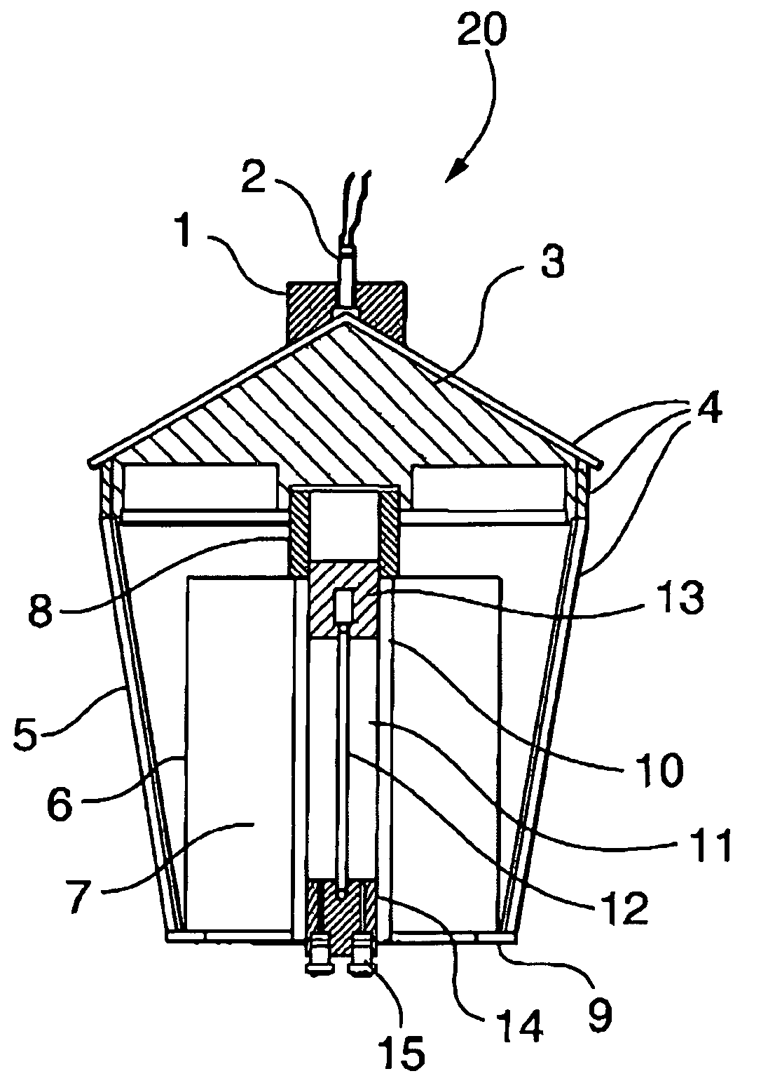
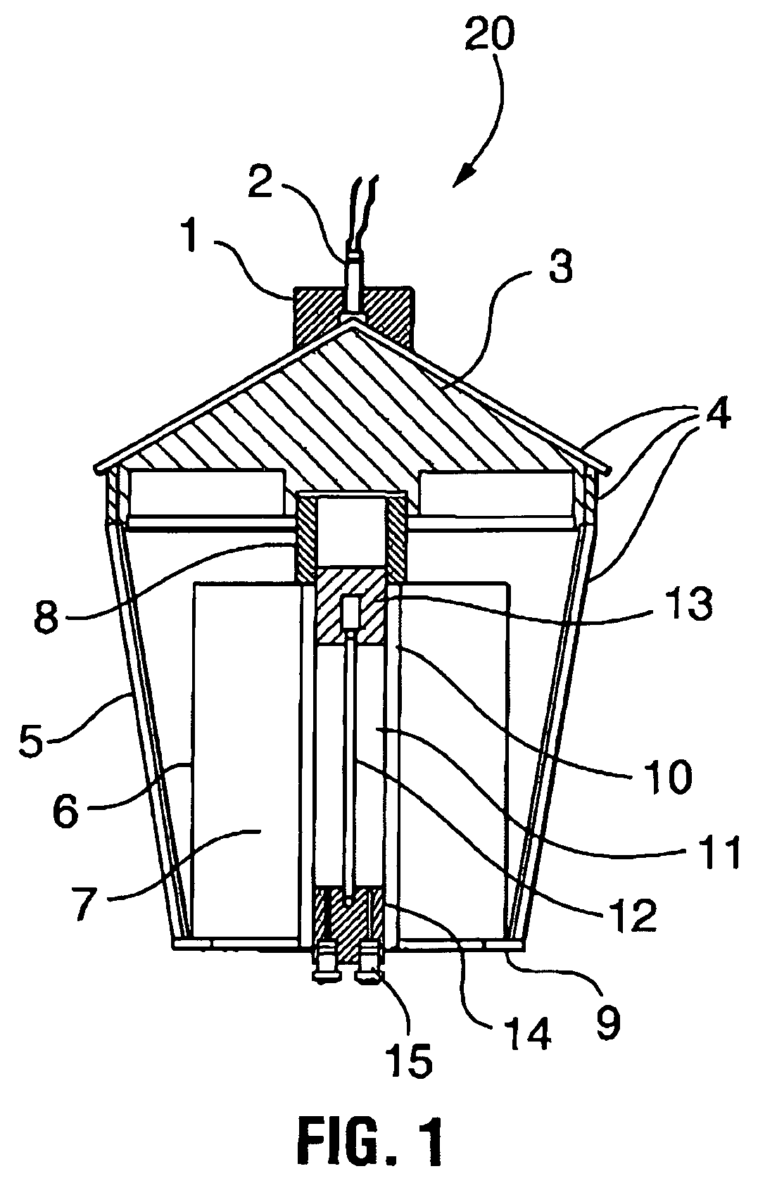
[0061]Referring now to FIG. 1, numeral 20 globally references the device. The arrangement has a conical metal flyer shell 5, base plate 9 and cone shaped lid 3. In use, the device is retained with lid 3 in position as depicted.

[0062]The lid comprises low density foam and provides sheets of explosive 4, which also clad the flyer shell 5 with the exception of the base plate 9. Mounted at the apex of the lid 3 is a detonator 2 secured to the former by holder 1. The device 20 positions a sample holder (discussed herein after) in coaxial relation with the apex of lid 3 and consequently detonator 2.

[0063]In greater detail with respect to the sample holder, the holder comprises a metal anvil 10 containing an insensitive energetic sample material 11. The anvil 10 has a top plug 13 and a bottom plug 14 which locate and retain a centrally disposed rod 12. A centering sleeve 8 ensures coaxial alignment of rod 12 and anvil 10 with lid 3 and detonator 2. In the case of liquid sample material, se...


PUM


Abstract

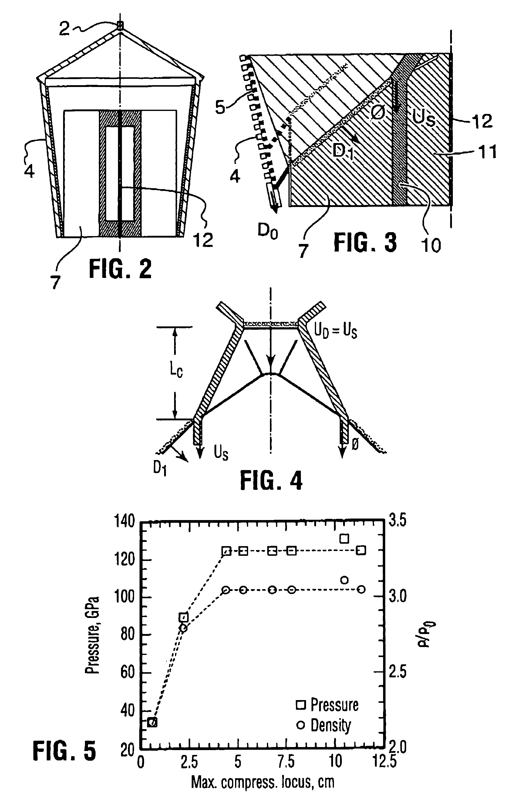
A method and apparatus are provided for detonation of a super-compressed insensitive energetic material by cylindrical implosion followed by an axial detonation to a detonation velocity several times that of TNT and a detonation pressure in excess of ten times that of TNT. The device provides a conical metal flyer shell within which is disposed a cylindrical anvil surrounded by explosive. The anvil retains an insensitive energetic material to be compressed and detonated. A first detonation of explosive by impact of the flyer shell generates a reverberating oblique shock wave system for sample compression. Axial detonation of the compressed sample through any length of a sample is achieved following the principal of matching the axial velocity and compression time of the oblique shock wave system to the detonation velocity and induction delay time of the compressed sample. The method and apparatus are also applicable to enhancing the effect of anti-armour and anti-hard-target munitions. The apparatus is also applicable to inert sample compression to the megabar range without using the axial detonation.

Description

CROSS-REFERENCE TO RELATED APPLICATIONS[0001]This application is a continuation-in-part of U.S. patent application Ser. No. 10 / 459,714, filed Jun. 12, 2003.FIELD OF THE INVENTION[0002]The present invention relates to super compressed detonation and more particularly, the present invention relates to detonation of super-compressed insensitive energetic materials to alter the physicochemical and detonation properties and a device to effect this result.BACKGROUND OF THE INVENTION[0003]A panoply of efforts have been purported to affect materials by high-pressure compression. Exemplary of the techniques having been established include the use of diamond anvil technology for the compression of molecular solid hydrogen above 3 megabars. The process was useful in terms of generating a significant density increase and phase transformations. This work was further augmented by others where solid nitrogen was compressed into the megabar range where it was then observed to provide a semi-conduct...

Claims


Application Information

Patent Timeline
Patent Type & Authority Patents(United States)
IPC IPC(8): F42B10/00F42B1/00F42B12/06
CPCF42B1/00F42D3/00
Inventor ZHANG, FANMURRAY, STEPHEN BURKEHIGGINS, ANDREW
Owner HER MAJESTY THE QUEEN AS REPRESENTED BY THE MINIST OF NAT DEFENCE OF HER MAJESTYS CANADIAN GOVERNMENT
Learn More